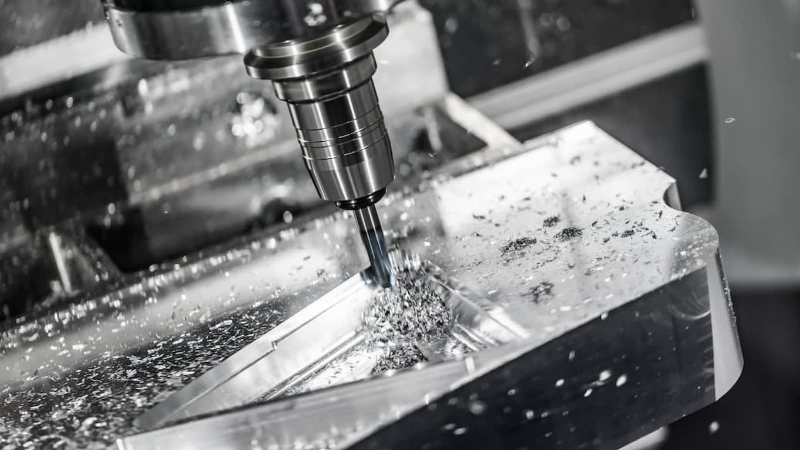
Die casting is a significant process for applications in various industries. An essential component of the die casting process is the die casting mold. The shape and characteristics of the mold affect the features of the final product.
Therefore, there is a need to understand the die casting mold design. This will help you design and choose the right mold for your die casting projects. Furthermore, you can be sure that the final product will meet unique manufacturing requirements.
Thus, this article will give you a detailed overview of the different types of die cast tooling. You would also learn how to design a mold and the factors you need to consider when making die casting tooling.
Why is Mold Important for Die Casting?
The design of the die cast mold plays a vital role in the shape of the part. In addition, it affects the quality, uniformity, and configuration of the components from the die casting process.
Wrong specifications can result in material or tool corrosion. Nevertheless, a proper mold design can boost the product’s time and efficiency. Ultimately, the quality of mold structure will determine whether production would proceed smoothly and castings would be of the best quality.
Moreover, the die cast tool design essentially reflects the different factors that may occur during production. Thus, you must analyze a casting’s structure during design. It is also essential to master filing conditions, implement critical process parameters, and consider other economic effects. This will ensure that die casting tools can meet essential production requirements.
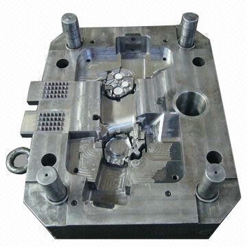
Die Casting Mold Components
Understanding the die casting mould begins with the knowledge of the mold structure. The essential die cast mold components include:
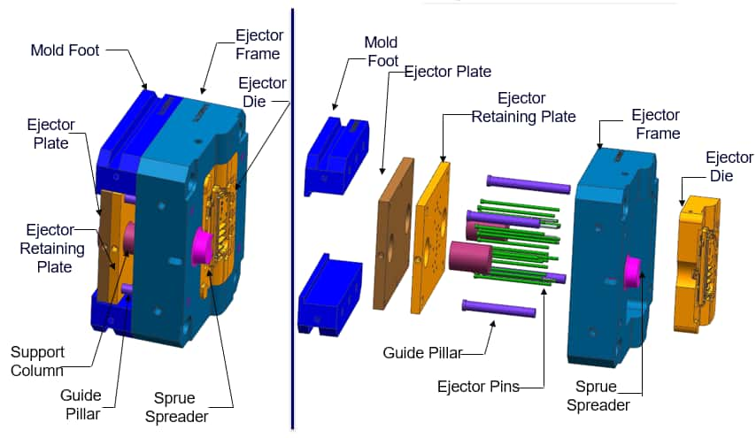
· Molding System
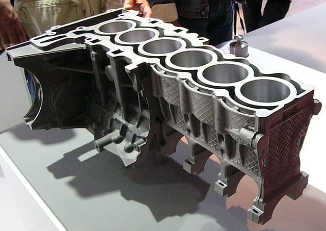
This includes the cavity, core, inserts, sliders, and insert pins. The die casting cavity determines the casting shape as the moving core closes.
· Mold Base System
The primary components of the die cast mould base system are steel plates and frames. This system combines different parts of the mold and allows mold installation on the die casting machine.
· Ejection System
This system works to eject parts from the mold. These parts include ejection, returned, and guiding parts.
· Runner System
The runner system connects with the die casting part and pressure chamber. Thus, it guides the metal material into the die cavity in a specific direction. This system directly impacts the pressure and speed of molten metal. The runner system components are a runner, a sprue, an inner gate, etc.
· Overflow System
This channel removes air from the pressure chamber. Generally, the primary components are overflow slots and venting slots. However, manufacturers install vent plugs in the deep cavities to improve venting conditions.
· Others
Other die casting mold components include positioning parts for placing parts correctly in the mold. In addition, there are pins and bolts for fastening purposes.
Types of Die Casting Molds
There are several types of die casting toolings, and they have different functions depending on the requirements. They include:
Prototyping Dies
A significant investment in die casting is a fully-featured custom-made die. Therefore, a prototype die helps to make quite a number of casts to test for the different parts. The prototyping strategies are gravity casting, machined hog outs, and 3D printed parts. However, they involve trade-offs on properties, tolerance, and design.
A high-pressure die casting prototype will be your best option whenever you need the same alloy, properties, process, and geometry in place for production. Prototyping dies can utilize pre-hardened, uncoated tool steels and standardized components. As a result, they can be produced in short times and at a reduced cost.
Unlike other production techniques, these molds also make use of less efficient ejection or cooling techniques. Therefore, you must note that the tool won’t last for long, and the die won’t be as efficient as a production. However, this will not be an issue if you only need a small amount of casting.
Rapid Tooling Dies
Rapid tooling refers to inserts and dies produced using methods with shorter lead times than conventional methods. As opposed to rough machining and heat treating, the rapid tooling methods are selective laser sintering, direct metal deposition, laser engineered net shaping, etc.
Therefore, you’d expect the creation of these die cast tooling dies to be much faster. Manufacturers may use these dies either as prototyping dies or as production dies. The most viable choice will depend on the production volume requirements.
Production Dies
These dies are the most common types of die casting dies. Production dies are essential when all the design has been finalized and is ready for launching into an authentic product.
We can have:
- Single-cavity dies with no slides
- Multiple-cavity dies with several slide options
The cavity material is high-quality steel, and it is often retained in a holder block. The design of production dies ensures that they have critical dimensions. Thus, you can be sure that they allow the required machining specifications.
Unit Dies
The unit die is a special type of die casting mould. A die caster unit holder keeps the unit dies or customer-owned cavity within the cavity intact. We can have either single or double unitholders. Typical examples of sizes of cavity blocks that the dies hold are 8 x 10, 10 x 12, 12 x 15, and 15 x 18 (all in inches).
The unit dies employ generic pieces used for less complex components with a low volume. A custom die is more effective for higher volume parts with complex geometry. These dies are specifically designed for a part, providing maximum control and efficiency.
Trim Dies
CMW uses trim dies for high volume production and the production dies. The trim die trims off the flash, runner, and overflow from the part immediately casting is complete. Some trim dies need hydraulic operated motions or cam, whereas others require open and close functions to remove the flash effectively.
Part geometry prevents the ability to remove the flash with a trim die totally. So, hand de-flashing strategies and custom trimming service is an ideal option in this situation.
Need modern-looking parts with better strength and higher durability? Choose die casting process requiring tooling to produce your end-use parts. And the good news is, RapidDirect’s die casting services provide you one-stop solution.
Mold Design Process for Die Casting
This section will describe the process involved in designing a mold for high-pressure die casting projects. The process has five broad categories:
Preliminary Phase
Before designing the mold, it is important to check the part’s manufacturability with die casting technology. This phase involves judging the practicability of the product from a geometrical and dimensional.
Dimensional View: There is a need to know the dimension of the part and the number of cavities required for each casting. This will help know the opening force and the volume of the casting. The knowledge of this data will make feasibility studies a lot easier.
Geometrical View: The geometry of the parts includes drawing the parting line. The parting line divides the die casting mold into two, allowing easy mold opening and ejection of casting. Furthermore, the surface of parts depends on their position from parting lines. Consequently, surfaces have to be designed in the direction of mold opening.
The geometric tolerance of quotes found on the 2D model can be pretty hard to produce due to the shrinkage caused by metal cooling. The higher the number of quotes, the more difficult it is to get the same value on the casting. Therefore, you can go ahead with the die cast mold design as soon as you confirm the part’s manufacturability.
Number of Cavities
To know the number of cavities, you must consider the number of pieces to produce, cavity orientation, and the hypothetical cycle time. This way, you can decide the best option between a multi-cavity or a single-cavity mold.
When going for a multi-cavity mold, remember that aside from the fact that ejection phases and complexity of filling increase, the production process might be affected by the cavity’s dimension and product disposition.
Projection Area
The projection area is the surface gotten from the projection of cavities on the plan. It is perpendicular to the direction of the mold opening. The projection area is a vital component of the design phase. It relates the opening force from the molten metal to the die walls. As a result, the strength of the force will depend on the shape dimension orientation. A strong force will cause an overflow of material, thereby resulting in the formation of burrs.
Therefore you need to estimate the forces produced by the molten metal to prevent this casting defect. The force is the product of specific machine pressure, projection area, and pre-set safety factors. The factor offers a wider margin to help counter the maximum pressure after filling. Many people refer to it as a water hammer.
The machine transfers the dynamic and static force at the end of the process. Thus, there is the production of a pressure pick that the closing machine force must absorb. This closing force depends on the stroke dimension and press model.
Volume and Shape of the Die
The volume and shape of the die are essential for mold design. In addition to the volume desired, consider that the large parts will shrink due to a longer cooling time, increasing the shrinkage rate. Therefore, there is the need to size the mold cavities accordingly.
Moreover, it is advisable to consider different variables that affect the final mold size. The most important factors to consider are:
Injection Channels: The size of injection channels varies with the number of cavities and the position of gates and pieces. The shape of injection channels has to meet some fluid dynamics requirements. For instance, manufacturers decrease the section to adhere correctly to the mold wall when moving in the direction of molten metal. Due to the shrinkage, there is an accelerated flux, and they’re detached from the walls. A smoother external layer will prevent turbulence, air trappings, and other defects.
Type of Die Closing: Open/close mold closing is the plainest die closing. It is best for products with clean, simple shapes that can be easily ejected. However, it is not the best option for parts with complex geometry. Products with complex geometry would be difficult to remove, so the manufacturer needs to add to the overall die size.
Presence of Overflows: Overflows are small wells designed in strategic parts of the die cast mold. They are important in collecting first metal shots because it is often colder than the following ones. As a result, you can avoid cold laps and other similar aesthetical defects. In addition, overflows serve as a heat source, increasing the die temperature in critical areas for final casting.
Simulation Through Semi-Empirical Modes
After the initial design stage is complete, the next stage is the simulation of die filling using semi-empirical modes. The simulation helps in calculating the modality of mold filling. Moreover, the modality depends on the function of the casted piece and the filling process. For parts with complex structures, it is best to induce compactness and mechanical resistance. Meanwhile, for aesthetic parts, the surface finish has to be top-notch.
The characteristics can be altered by varying the fill time. The quicker the filing, the higher the quality of the surface, while longer filling will impact more strength to the components. Once the analysis is complete, it is easier to notice if there will be any casting issues.
The aluminum die casting mold design starts with analyzing the manufacturability, then calculating the forces and checking the injection channels. The optimization and design of these channels are done through simulation to know filing mode and detect any issue. After successful completion of this stage, you can move on to producing the designed mold.
Factors to Consider for Making Perfect Die Casting Tooling
Before making die cast tooling, there are some things to look out for to guide in die cast tool design. They include:
Die Draft
The draft is the degree to which you can tamper with a mold core. You need a precise draft to remove the casting from the die safely. However, the draft is not constant, varying according to the angle of the wall. Thus, characteristics like the type of molten alloy used, the mold’s depth, and the mold’s shape can affect the whole process.
Another factor that can affect drafts is mold geometry. Generally, untapped holes need tapping because of the risk of shrinkage. Likewise, inner walls need more drafting than outer walls because inner walls tend to shrink.
Fillets
A Fillet is a concave junction that helps to smoothen an angled surface. A curved surface disturbs the casting process, so folds have fillets to produce a honed edge and limit the risk of production errors. Although there is an exception to the parting lines, you can add fillets to any part of the mold.
The fillet will increase the lifespan of the tool. To allow for continuity of smoothness, make a constant-radius fillet. Furthermore, tools that have a deep inside will need larger fillets.
Parting Lines
Parting lines, also known as parting surfaces, join various mold sections together. If the parting line is deformed due to work strain or it is wrongly positioned, materials can pass through the space between the mold pieces. This may lead to excessive and non-uniform seaming.
Bosses
Bosses are die-cast knobs that serve as stand-offs or mounting points in die cast tooling. Manufacturing industries usually add a hole to the internal structure of the boss to make sure the walls have a uniform thickness. It is challenging to fill bosses with metal, and thus, ribbing and filleting are essential to eliminate this issue.
Ribs
Die casting ribs to help improve the strength of the material for a product lacking the desired wall thickness. Selective rib placement improves fill capability and decreases product weight. It also reduces the occurrence of non-uniform thickness and stress cracking.
Holes and Windows
Having holes and windows in aluminum die casting mold allows for the creation of substantial drafts and ease in removing a completed mold. However, features like flashovers, cross feeders, and overflow are necessary to prevent material flow and unwanted cast in the holes. Holes and windows are among the essential things in design geometry. They affect the flow of molten metal and play a vital role in the product’s final quality.
Symbols
Manufacturers always add product logos or brand names in the mold design in die casting. Some casting has a date to differentiate a batch from another batch. Although symbols do not make the design process complex, they can add to the cost of production. A raised logo will require a different metal for every manufactured part, while an indented symbol will require a lesser amount of metal.
Wall Thickness
Die castings have a thin wall that has no fast and hard rules for maximum and minimum wall thickness. It is necessary to create a uniform wall thickness throughout the part. Uniformity will provide a smooth metal flow when filling and reduce distortion resulting from cooling and shrinkage. The main aim is for the die casting mould to fill before the solidification process to prevent cold shuts.
RapidDirect Chasing for Perfect Die Casting Parts
Understanding die casting mold design will make your die casting project easier. It will also help you save some time and money. However, you need the service of experts to get the right tool for the best results. RapidDirect offers the best precision die casting services for custom metal parts, providing quality tools, experts, and easy processes.
We have a wide range of materials, manufacturing processes, and surface finishing options for your die casting parts. Also, our experts offer you manufacturing suggestions to ensure you get the most effective solution. After placing the order for die casting parts, RapidDirect manufacturing partners would produce perfect die casting tooling to make the best die-casted parts. Upload your design file today and get an instant quote.
FAQs
For permanent mold, the metal flows directly into the cavity from the reservoir. The molten metal is forced into the cavity under high pressure in die casting.
The mold consists of two parts – the ejector and the stationary part. It contains the space forming the dimension and contour of the casting. The mold is also known as the die, and they are made from hardened steel to meet the shape requirement of the die casting part.
Molds production involves passing a molten metal under high pressure into a metal die. The creation of the mold occurs in sections to allow for easy removal before placing them in machines such that one is removable and the other is fixed. The molten metal would pass through the cavity, and it will then solidify.