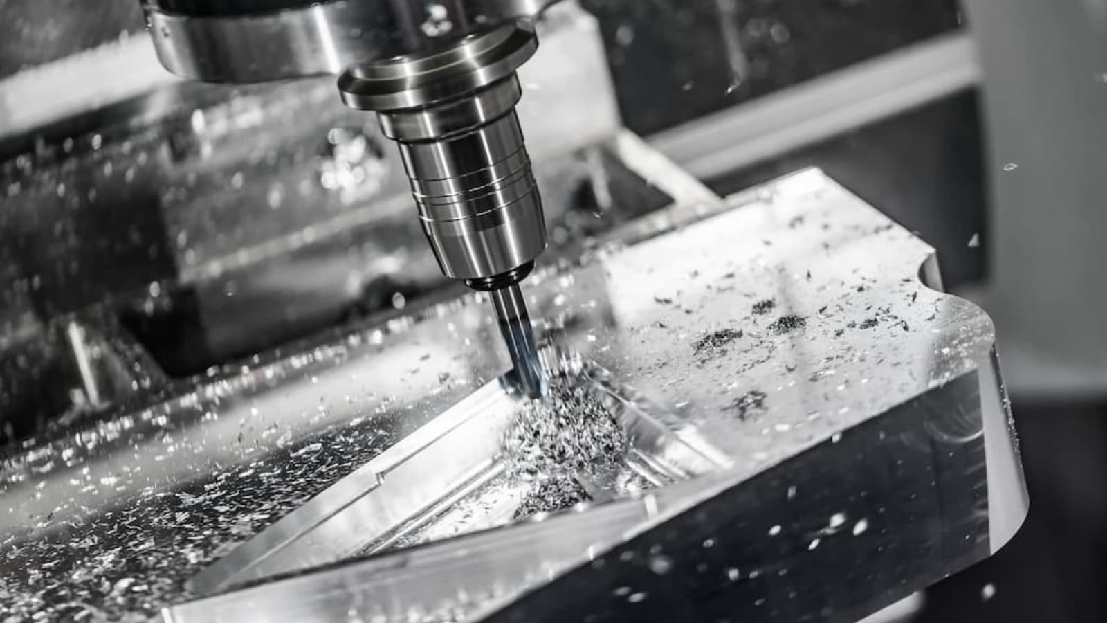
Drawings and pictures are among the best means of communicating one’s ideas and views. This is even truer for engineers and machinists. Understanding the basics of engineering drawing is a great first step. This will allow you to communicate the intent of your design for CNC machined parts.
Most rapid prototyping customers upload design files and drawings for a better understanding of requirements. However, not all engineers are comprehensively trained to create clear drawings. This can create challenges for manufacturers who may not easily understand the drawings. Thus, there may be substandard formatting and negative impacts on costs, lead time, and specification clarity.
This guide seeks to put you through technical drawing basics. We’ll also give you 8 important tips for creating better engineering drawings. That way, you can learn how to create engineering drawings effectively. This ensures that you can communicate your unique ideas and requirements clearly. Thus, you will save yourself some time and money.
What is Engineering Drawing?
An engineering drawing (also named as mechanical drawing, manufacturing blueprints, drawings, dimensional prints, and more) refers to one of the technical drawings, which helps to define engineering products’ requirements. Basically, this type of drawing aims at clearly capturing all the geometric features of products and their components. This will ensure that manufacturers can produce parts that meet specific needs.
The mechanical drawing includes a description of the manufacturing process. Thus, it conveys engineering ideas for a design process. It may also provide records of already existing components. Engineering drawing is not just an illustration. Rather, its intention is to describe the shapes and sizes of components.
Such descriptions may also include specifications of acceptable variations, limits, materials, and others. The drawings can be of various forms, ranging from oblique to isometric. The drawings also include a series of projections that show various angles of the components. All of these are aimed at getting the products to meet requirements.
The Purpose of an Engineering Drawing
As already mentions, this mechanical drawing includes every piece of information needed for manufacturing components. The information may include dimensions, part numbers and names, variations, tolerances, and more. Therefore, an engineer can start the manufacturing process immediately after he gets the drawing.
How to Make an Engineering Drawing
In past years, all that was available were drawing boards, papers, rulers, calipers, and others. While these instruments are still available today for manual drawings, such drawings are not suitable for contemporary manufacturing.
This is because most CNC systems today can read the information right from the files. Thus, they can easily produce a cutting program as required. Handmade drawings would just make this more cumbersome for engineers.
The advent of computer-aided design (CAD) software has made things a lot easier. This software comes with several advantages over manual drawings. You can use CAD to make drawings from scratch. However, the easier option will be first to make a 3D model. Then, you can create your drawings from there.
All you need to do, basically, is to include the dimension. The CAD program generates views with just a few clicks. The 3D models will make it a lot easier to update drawings for revisions.
After you make great engineering drawings that show your special requirements, you can upload them to the RapidDirect platform that provides professional prototyping manufacturing services.
Basic Components of an Engineering Drawing
Creating drawings for optimum production will require a good understanding of technical drawing basics. A single drawing consists of several elements with a few variations to them. Let’s take a closer look at the components that make up an engineering drawing, and then you would know how to read engineering drawings.
Types of Lines
Note all the lines you find on an engineering drawing are equal. There are various options available, making it possible to show hidden and visible edges of parts.
The most common type of line is the continuous line. Many people refer to this as a drawing line. It represents an object’s physical boundaries. That is, it is a type of line used for drawing the object. The thickness of the line varies. Outer contours use thicker lines, with inner contours using thinner ones.
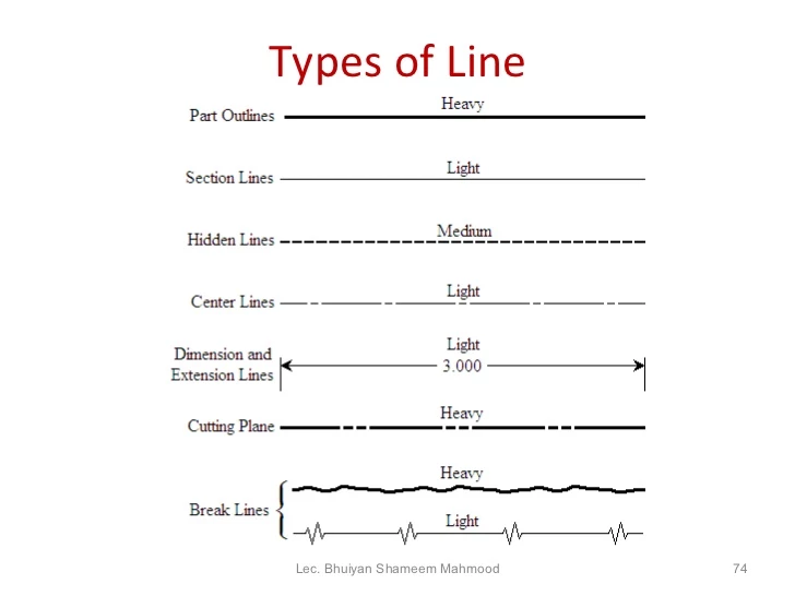
The hidden line is another type of line used in mechanical drawing. It helps to show points that would not be otherwise visible on the drawing. For example, the length of an internal step of a part may be shown using hidden lines.
Centerlines show holes and symmetric properties of a part. Extension lines can annotate an area that is being measured. On the other hand, break lines show a broken view without taking too much space.
Different Types of Engineering Drawing Views
There are various types of views in an engineering drawing. Each of them serves different purposes. Note that you should only include a view that contributes to a design’s overall understanding.
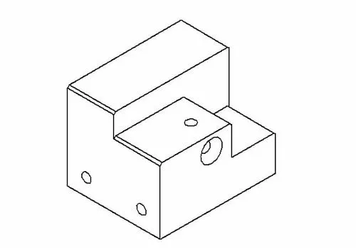
Isometric View
Isometric drawings show a three-dimensional view of parts. Vertical lines remain vertical, and parallel lines come at a 30-degree angle. The lines in this type of view are in their true length. With this type of view, engineers stay true to the dimensions instead of using optical illusions.
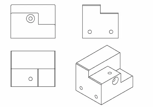
Orthographic View
This is one of the most preferred views in an engineering drawing. An orthographic projection helps to represent a 3D object in 2D. This ensures the conveying of everything needed for the production of components. Also, there is no distortion of the length of any kind.
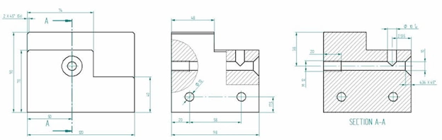
Cutout View
Cutouts help to reduce the different kinds of views we can have for a single drawing. It is a great option for including every necessary dimension of a cutout.
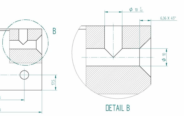
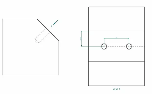
Detail View
A detailed view shows a close-up of specific sections in a larger view. This is useful if there are important dimensions in that small area. It is a good view of the readability of measurements.
Auxiliary View
This type of view helps to represent planes that are not vertical or horizontal. It shows inclined surfaces without distortions.
Dimensions
As already mentioned, new CNC machines can read dimensions right from the line. Some crucial bits of information may be missing from CAD models. This may include tolerancing GD&T and geometric dimensioning.
The right dimensions always guarantee a long lifetime of components with lesser maintenance. You can fetch dimensions automatically via the measure button. However, including engineering tolerances requires manual action.
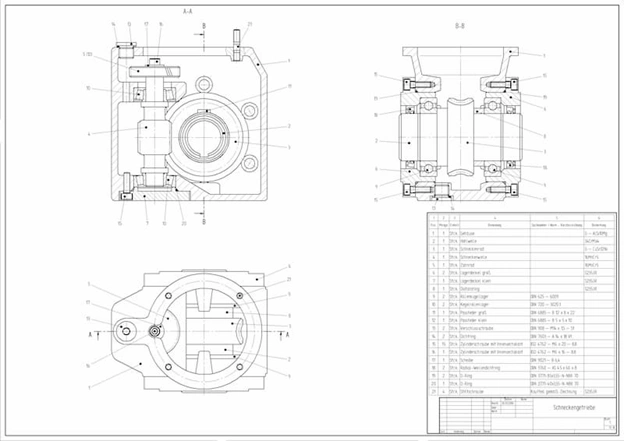
Information Blocks
These are little boxes present at the bottom corner of the engineering drawing. The block includes part name and number, author’s name, coating, quantity, scale, and other information. These information blocks may also include the prices of materials. Every component used in the assembly must also be included.
Here’s also a video about engineering drawing basics.
Important Tips for Improving Engineering Drawing
The following tips will help on how to improve engineering drawing skills. This way, manufacturing engineers can easily understand the requirements for your components.
Tip 1: Include Dimensions of Only Critical and Measurable Features
In CNC machining, the 3D model often contains all dimensions needed for manufacturing. Therefore, you should only include critical threading information and critical inspection dimensions on your mechanical drawing.
Tip 2: Add Hole Tapping Needs to Your Drawing
It is often hard to measure thread depth exactly. Therefore, you should always tread the depth call-out as a minimum.
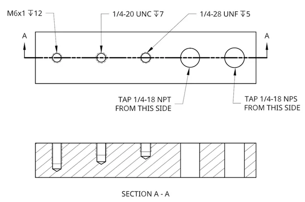
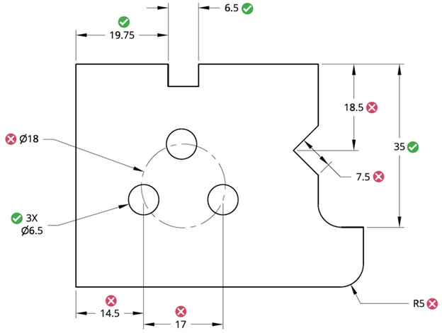
Tip 3: Consolidate Call-Outs
If there are multiples of the same feature in a view, give a dimension of only one of those features. You can then label the dimension as “#X DIM”. This means that the feature exists in the view X number of times. For example, “5X 10-38 TAP” means that there are 5 10-38 threaded holes in that view.
Tip 4: Communicate Assembly Intent of Crucial Features
If the production involves the machining of an entire assembly, you should include an assembly instruction in your engineering drawing. Also, you can provide part numbers for your machinists to look up. This is especially important if you’re installing off-the-shelf hardware yourself.
Tip 5: Part Numbers are Very Important
In a case where hardware installation is needed, the supplier and part number should be provided on the drawing. Just noting “press-fit M4 dowel” does not give material information or machine shop dowel length.
Tip 6: No Need to Include Optional Secondary Operation Call-Outs
For non-critical operations such as polishing and anodizing, you can leave them out of your mechanical drawing. It’s often best to request quotes and lead times for these operations separately. This way, you can know the additional cost and time. You can also leave the material off the drawing if you’re unsure of the type of material to use. This will help prevent confusion on different levels.
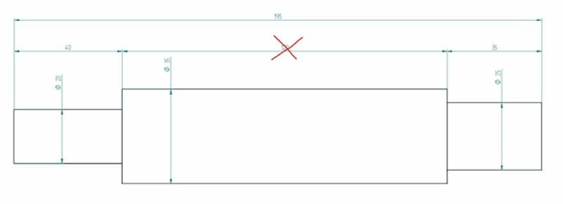
Tip 7: Avoid Over-Dimension or Over-Tolerance on Your Designs
Usually, only some of the features of components are crucial to its function. Therefore, you would want the machinist to focus more on these features. Over-dimension could lose the critical features in the noise. It is, therefore, important to assign tolerances to only function-critical features.
Tip 8: Tolerance Must Fall Within Standard Accuracy Levels
It is important that you give the right level of tolerance for your material. Do not require tolerance that falls below the accuracy capabilities of standard hand metrology tools. Therefore, you should research the started measurements used at your preferred machine shop. This will help you make informed decisions.
Conclusion
Engineering drawing remains a big aspect of a machinist’s job. These drawings contribute up to 20% of design work time. This helps to clearly capture all the geometric features of products and their components. That way, you can be sure that manufacturers can produce parts that meet specific needs.
At RapidDirect, we seek to save time by automating 3D model reading for production purposes. This leaves engineers with the responsibility to produce GD&T and assembly drawings only. The aim of this process is to help us focus on manufacturing better products.
We boast strong manufacturing capabilities with services that will meet your customized requirements. We help optimize your part design using the most robust tools available. All you have to do is upload your design file, and you’ll get an instant quote. These and many more are available at competitive prices.