The design of any manufacturing process is just as important as the machining itself. One of the most important languages used in the design is geometric dimensioning and tolerancing (GD&T). Several engineers implement GD&T symbols during the part design.
It helps to optimally control and communicate these variations to ensure it is well minimized and doesn’t affect the efficiency of the parts being designed. GD&T is a symbolic language and an acronym for geometric dimensioning and tolerancing.
This article will explain the various symbols used in GD&T, how it works, and its various applications.
What is GD&T
Geometric dimensioning and tolerancing, shortened as GD&T, is a system of symbols and standards which engineers use to communicate manufacturing information. They also use these symbols for several other reasons, including:
- Provide a suitable definition for production and inspection processes.
- To make mating parts fit well together.
- It indicates limits that shouldn’t be crossed even in the worst-case scenario.
- It is a universal language; thus, it is well understood across the board regardless of the person you’re working with.
The GD&T is not a newly introduced system in the manufacturing field. It has been around since 1938, and it has helped a lot in the manufacturing processes ever since. Stanley Parker is responsible for developing this symbolic manufacturing language.
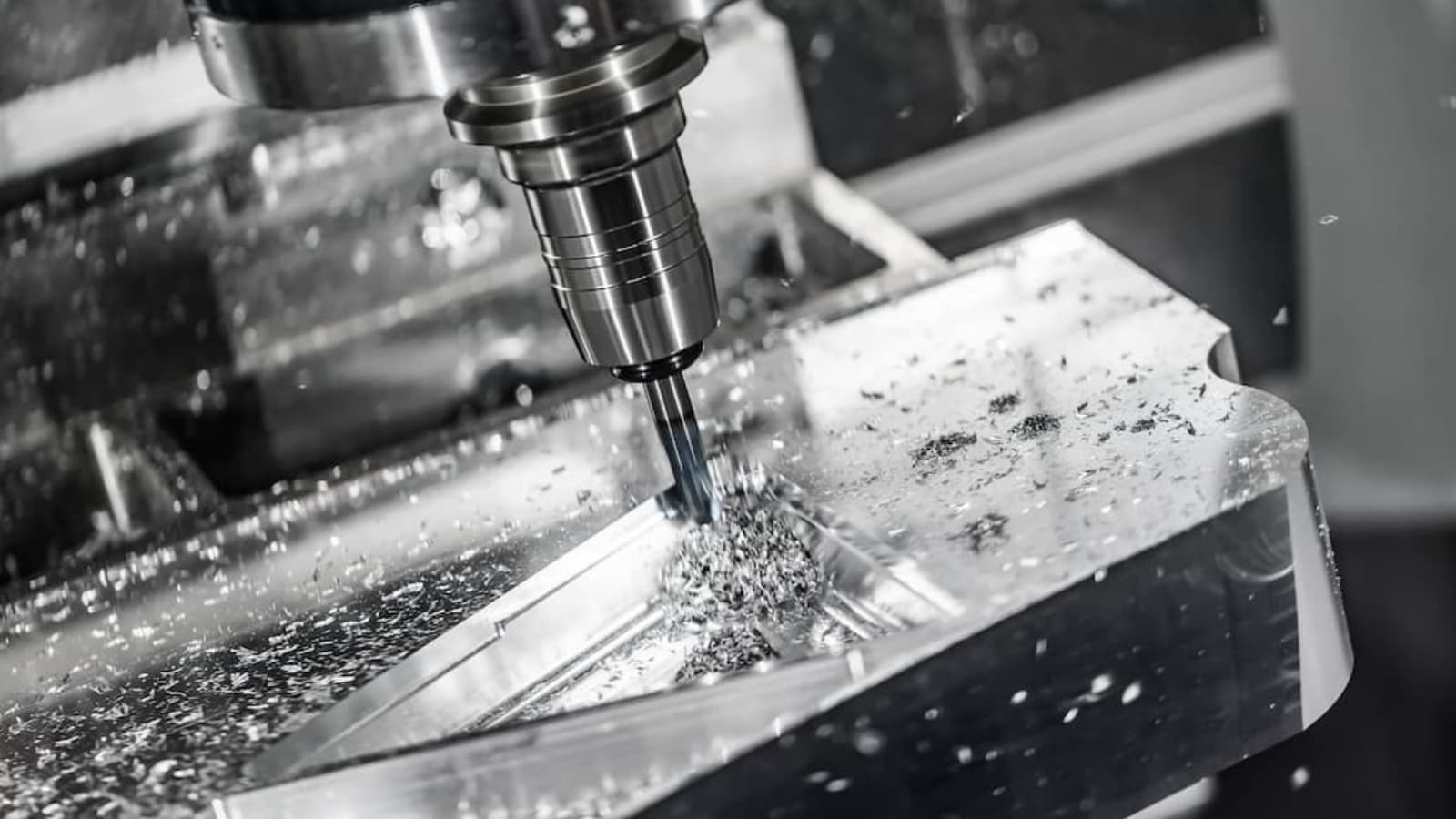
GD&T is crucial in the manufacturing industry, and it is essential in creating any parts that require CNC machining services, especially in CNC machining processes that require tight tolerances.
If you need a system that solely focuses on your design’s geometry, then the GD&T will work fine for you.
Importance of GD&T
Since there are traditional ways of determining tolerances and dimensions, why do we still need Geometric dimensioning and tolerancing?
This system has some unique importance, and they include:
Excellent assembly
With the traditional method, you can design accurate individual parts. However, a major setback to this method is that they don’t guarantee how well the individual parts will interact when coupled together. This is why you need GD&T.
Some parts cannot function alone independently, but they are essential parts of a larger compartment that perform a specific function. Now, imagine if that part doesn’t integrate well at the assembly level. It can affect the efficacy of the whole component.
For instance, consider the case of a connecting rod. A connecting rod is not beneficial on its own until it is connected to a larger part where it is required to play a major role. If you connect it to a piston and crankshaft, you’ll see it performing a useful function. In that case, it helps to make a rotational motion out of a linear motion. If you connect this assembly to a larger component like a generator or diesel engine, you see it performing a better function as those machines serve different purposes.
It is, therefore, essential that parts integrate and mate well with each other. This is how GD&T can help you. With it, you can guarantee that your parts will fit well when integrated into a larger component.
Universally understandable
The geometric tolerance symbols are universally understandable. This makes it easier for engineers to communicate their ideas to others in the field. Its rules, vocabulary, and definitions are straightforward. Thus, it helps the designer to communicate his intentions.
It saves time and money
If your design doesn’t fit well for its intended use, that may require you to work out a new design. You may have to keep repeating the cycle until you have a perfect parts design that works for your component. This will not only waste your time, but it is also a waste of resources.
You can eliminate this stress when you use GD&T. It helps to ensure that you have a perfect design once and for all. Hence if you want to cut down wastage and get a lot done on time during your manufacturing process, you should consider GD&T. It also makes it easier for you to communicate your ideas with others. Therefore, it saves you time and energy.
Also, using GD&T symbols on your design puts some sort of quality assurance on the work. This way, any other engineer can pick up the design and understand the various dimensions and tolerance values spec
How does it work?
GD&T works on a simple principle. It works by specifying the required dimensions and tolerance value of a design. The tolerance value of a design is usually between the minimum and maximum limit. In other words, it is the difference between the maximum and minimum limit.
To appropriately tolerance the product and ensure it doesn’t go beyond or below the maximum and minimum tolerance, we need GD&T symbols. It is a symbol that helps to communicate the design intent and ensure it perfectly fits the role it’s meant for. It’ll be more challenging to communicate such control with traditional plus-minus tolerancing.
GD&T Symbols
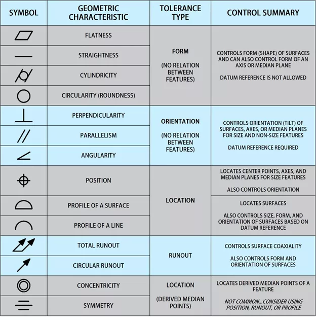
Geometric dimensioning and tolerancing symbols have five different groups. Each of these groups has different symbols. They include:
Form controls
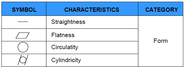
Symbols in this group are used to specify shapes. They include:
Straightness: This is further categorized into two-axis straightness and line element straightness. This geometric tolerance symbol indicates the part surface must remain with the tolerance area and stay flat.
Flatness: The symbol indicates how flat a surface must be regardless of any other features. Flatness is usually measured between the highest and lowest spot on a surface.
Circularity or roundness: This symbol indicates how closely a feature resembles a perfect circle. It also means the feature must have no features or edges.
Cylindricity: This geometric tolerance symbol indicates how closely a feature must resemble a perfect cylinder. The Cylindricity of a design is difficult to inspect, and this is because it is a more complex symbol.
Profile controls
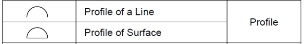
You can use a profile control if you need to describe the three-dimensional tolerance zone around a surface. It is further categorized into two, namely:
Surface profile: Surface profile is a complex control usually measured with a CMM. It is used in creating two offset surfaces.
Line profile: You can use this to compare a two-dimensional cross-section to an ideal shape.
Orientation control
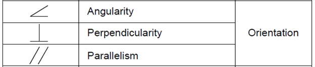
This contains dimensions with varying angles. It comprises of:
Angularity: angularity is determined through two reference planes. It is flat at an angle to a datum.
Perpendicularity: This indicates flatness at angle 90 to a datum.
Parallelism: This is a parallel line at a specified distance
Location controls
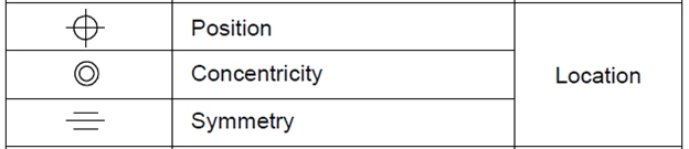
It uses linear dimensions to make well-defined locations. It includes:
Position: Like the name sounds, it is the location of a feature relative to the other or datums. The position is the most commonly used control.
Concentricity: You can use this symbol to compare the location of features to the datum axis.
Symmetry: This helps to ensure that there are no irregularities in the non-cylindrical parts of your design. It is a complex control and a bit challenging to use.
Runout controls
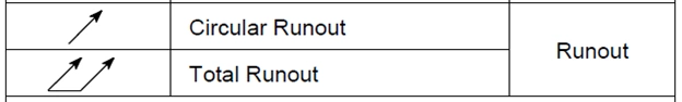
This indicates the accepted amount a particular feature can vary compared to the datums. Symbols under this category include:
Circular Runout: If you want to account for your design errors, you can use the circular runout.
Total Runout: You can use this symbol to describe the runout of an entire surface. It controls the profile, straightness, angularity, as well as other variations on your design.
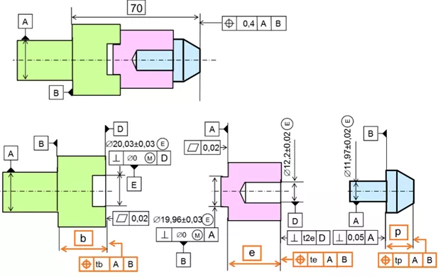
Feature control frame
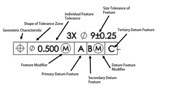
As the name sounds, the feature control frame controls the features of your design. It contains the instruction the design must follow. One feature frame can only carry one message. If you require two messages for a design, then you need to use two feature control frames.
The first compartment on this frame contains one geometric characteristic symbol. Recall that there are fourteen different symbols. However, you can only represent one on a single feature control frame. If you have two requirements, then you need two feature control frames. The symbol in the first compartment will dictate the requirement of the feature. For instance, it can dictate that the feature be flat or positioned.
The total tolerance for your design will be in the second compartment. The total tolerance comprises the shape of the tolerance zone, individual feature tolerance, and feature modifier. If you have a (⌀) symbol preceding the tolerance value, the tolerance has a cylindrical shape.
The third compartment contains the datum feature references. However, not all designs require a datum feature. You’ll need the datum feature if you specify a location tolerance such as position. On the other hand, if a form tolerance like straightness or flatness is specified, you don’t need a datum feature reference.
Conclusion
GD&T is a modern way you can adopt to describe the dimensions and tolerance of your design. It is better than the traditional plus/minus tolerancing which doesn’t guarantee the efficiency of the parts designed when integrated into a larger compartment. It is a generally acceptable symbol whose proper use can reduce the cost and time required for a specific design. If you want to ensure that the parts you design will fit perfectly for the role it’s meant to serve, then GD&T is what you need.
RapidDirect Machining Services

Machining parts isn’t a task you can assign to just any one. You need trusted hands who are veterans in the manufacturing world. That is why RapidDirect is the best choice for you.
Delivering parts that meet your quality requirements and expectations, you can rely on us to serve you right. Our strong manufacturing capabilities meet customer’s high tolerance requirements from all industries. We also offer full dimensional inspection before delivery.
We provide instant quoting and fast lead time. At RapidDirect, we know that you want the best service at a reasonable price. That is precisely what we offer.