As industrial designers, you wouldn’t want exposed fasteners to compromise the aesthetics of your products. The manufacturing environment today also calls for the efficient production of high-quality parts. This seems like an apparent paradox. However, the solution lies in using snap fit design to assemble parts.
Designing parts with snap fit joints can save time and money in production. They do reduce not only material costs and part quantities but also improve ease of assembly. The traditional injection molding technique has proved viable for producing the snap joint. However, 3D printed snap fit design has new opportunities.
Therefore, it is vital to understand snap fit design, and it reacts with the manufacturing systems. Snap fit designs come with certain challenges. This article seeks to help you navigate the complex snap fits world by discussing the key features. We’ll also look at the important classifications and the best practices to overcome common prototyping issues.
Snap Joint General Overview
Snap fit joints are among the simplest and most efficient ways to assemble parts. With snap joints, there is usually no need for different types of fasteners and tools. In its simplest form, a snap joint is a small protrusion that can be a stud, hook, or bead. The deflection of this protrusion occurs during assembly.
The main aim is to catch a feature in the main component. That is, the protruded part of a component may deflect while joining. Then, it catches a feature that is present in the mating component.
Usually, users won’t necessarily need to have access to the snap fit joints before assembly. This makes the automation of snap fit design a lot easier. The snap design also determines if the connection will be permanent or temporary. That is, whether the fits can be released by tools/force or not.
One of the important criteria in injection molding snap fit is the displacement of flexible features while assembling and disassembling. Snap joints are often employed in plastic parts. Therefore, flexibility is allowed with the fits. That is, plastic materials allow a reasonable level of strain and elasticity. Therefore, there can be large deflections without risking damage to the parts.
In a joined state, snap fits are usually free of load, and there is only minimal displacement. This makes them useful for plastic materials. Creeps tend to occur on stressed plastics, which may cause them to lose pretension over time.
In essence, stiff locator elements help to align joining parts. This helps to prevent any form of displacement and release of the fit from the joint. Catches, recesses, lugs, and others are good options in this case.
Snap fit joints are useful in a wide variety of applications. A few basic types of fits can be combined with them to meet industry standards and specific design requirements. This expands the diversity of plastic snap fit design examples.
Types of Snap Fit Joints
There is an extensive array of snap fit design possibilities available. This section’ll discuss the three most common types of snap joints. They include the following:
Cantilever Snape Joints
These are the most common types of snap fit joints in manufacturing. These joints have simple geometric shapes that make them easy to implement in a snap fit design. It is also easy to calculate their strain during the joining process.
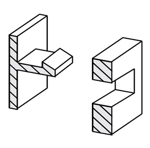
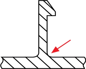
The basic design includes a cantilever beam that comes with a tapered hook at its tip. There is also a matching recess in the joining partner. The structure shows the tapered surface sliding along the joining partner’s surface. This bends the cantilever allowing the hook to reach the recess before snapping back into the undeformed state.
The joint can either be permanent, or it can support release at a separation force. This attribute depends on the surface angle occurring between the hook and the recess. In some cases, the cantilever does not come as a straight bar. There are other designs with U-shaped or L-shaped cantilevers. These designs are common in plastic parts.
These shapes have advantages in that they support longer cantilevers without taking up more space. Thus, they allow lower deflection forces when they are in compact environments. When these U- and L-shaped cantilevers are on the edge of a part, there won’t be a need for sliders in the injection molding design.
Torsion Snap Joints
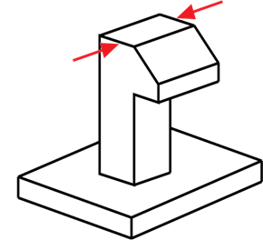
Unlike in the cantilever snap fit design, torsion snap fits basically deflect beams by twisting a bar. They are simple ways of creating separable connections. These robust solutions also amount to an economical and sophisticated joining method. The rocker arm’s design allows for the easy opening of the joining partner.
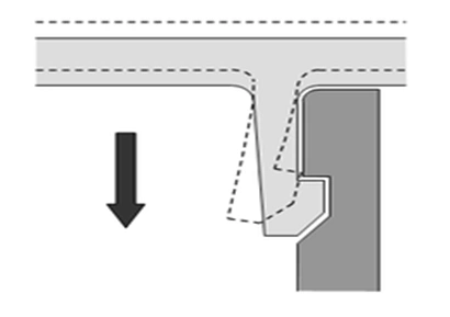
The deflection force of the rocker’s arm is given by the torsion of its shaft. The snap fit rocker arm and the torsion bar are integrally molded for the best connectivity. A seesaw mechanism occurs when there is an extension of the hook’s beam beyond the torsion bar axis. The user only needs to push the beam’s free end to lift the hook and release the joint.
Annular Snap Joints
A Snap design that uses annular snap joints is usually for elliptic or circular parts. These parts include pen caps and container lids. This type of snap fit joint comes with a ridge at the circumference of one component. This ridge locks into the groove of the second component. Aside from bending, tensile or compressive hoop stresses may occur during assembly.
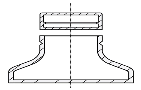
These multiaxial stresses can come as a challenge while designing a joint. We can estimate the strain of simple circular geometries based on the diameters of the joining components. Annular snap fits have a key property, which is the compression and stretching of the circumference.
People often confuse the circular arrangement of hooks for an annular snap fit design. However, this is not so because the deflection in annular fits is bending-dominated. Annular snap fits may exhibit varying properties depending on the design of the joining components. They are often easy to lock and release, as you will find in pen caps. Some may offer a permanent, non-releasing connection that depends on the angles of the joining components. Rotation may, however, be permitted in both situations.
This video shows you snap-fit joints for plastics:
Snap Fit Design Calculations
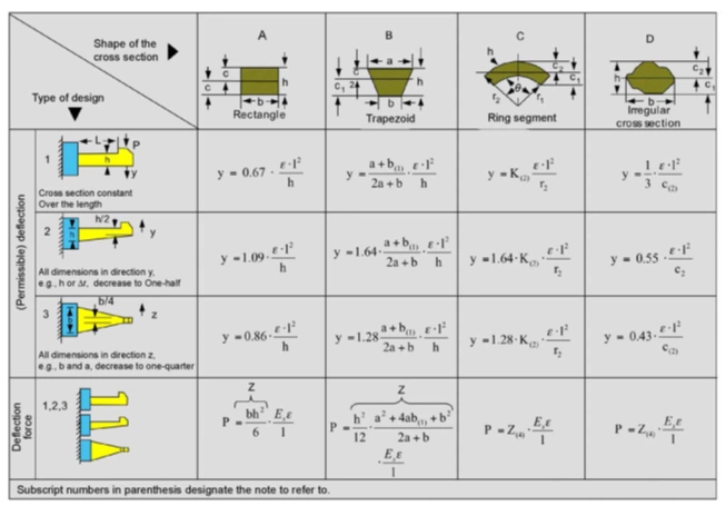
The calculations you’ll make for your design will depend on the type of design you wish to achieve. The following table will help you carry out effective calculations.
Symbols
- y = permissible deflection
- b = width at root
- c = center of gravity (i.e., the distance between outer fiber and neutral fiber)
- E as absolute value = percentage/100
- E = permissible strain in the outer fiber at the root
- l = length of arm
- K = geometric factor
- h = thickness at root
- Es = secant modulus
- P = permissible deflection force
- Z = section modulus
- Z = I c; where I = axial moment of inertia
Snap fits is indeed a cost-effective solution to the assembly of plastic parts. If you need any suggestions or have any prototype part needs, RapidDirect is your choice.
Common Snap Fit Design Problems and Best Practices
Snap fit design is not a one-solution fits procedure. Some challenges may arise during the injection molding snap fit or 3D printing process. Here, we’ll discuss some of the challenges engineers face when they design for snap fits
Stress Concentrations
When sharp corners occur while using the cantilever snap joint, stress may concentrate at the root. This causes the cantilever to be more susceptible to shearing off.
Occurrence of Creep
Plastics or thermoplastics are generally susceptible to creeping. This is a gradual deformation when the materials are under stress. Over time, the creep will compromise the connection between components and may render them useless.
Repetitive or Fatigue Loading Failure
When there is repeated assembly and disassembly of snap fits, there may be a failure at stresses that are lower than the material’s stress. Fatigue failure often occurs at high loading frequencies.
Tolerance Issues
When gaps are not rightly placed, tolerance issues may occur. Whenever there are tolerance issues, components won’t fit together perfectly.
More: Injection Molding Tolerance: Optimize Them in Four Ways
Engineering Best Practices for Snap Fit Design
There are various design features that can help reduce strain and stress on the snap joint assembly. They include:
Fillet the Base of the Cantilever
Adding a fillet to the base of the cantilever is a great way to distribute stress over the parts and create a stronger connection. The recommended fillet radius should be at least 0.5x the thickness of the cantilever base.
Taper the Design
Good design practice is to diminish the cross-section of the cantilever beam over its length. This ensures the use of fewer materials, and there will be a more even distribution of stress in the material.
Increase the Width of Clip
The aim of this practice is to add strength to the snap fit design. This may be an initial trial and error-process to get the right level of stiffness. However, the recommended clip width should be at least 5mm.
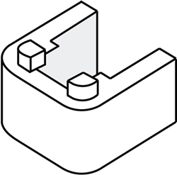
Consider Adding Lugs
The addition of lugs to an assembly will help with the alignment of parts. It will also help transfer some shear force from the clips.
Consider the Build Direction
It is advisable to avoid designing snap joints built from the bed vertically upwards. These are usually weaker because of the anisotropic nature of the process. The cantilever or other snap fits should also only be deflected during assembly. They should not be deflected during component connection.
Conclusion
Snap fits offer manufacturers cost and performance utility. However, snap fit design can be a complex and iterative process. Therefore, you only need to follow some simple manufacturing best practices to get the best out of your snap fit joints. This will further decrease prototyping life cycles.
RapidDirect is your go-to for all snap fit design solutions. Plastic fabrication is a crucial aspect of our prototype processes. We boast of engineers who are specialists in relevant processes and technologies. High-quality on-demand services are certain when you choose RapidDirect. You’ll get all of this at competitive rates. All you have to do is upload your design files for an instant quote.