Most engineered products are synced between two or more components that fit or slip over each other to deliver their primary functions. However, achieving this comes with understanding fits and the different types of fits used in mechanical engineering.
This article would explore what are the different types of fits. This will be in terms of the different types of fits you can use in your products’ designing stage. It will also introduce how you can choose the right one. Let’s dive right in.
What is a Fit?
Engineered products sometimes come as components that must slip or press against each other to deliver their functions. Therefore, a fit is used to describe these dimensional relationships between the components. It is used to determine whether the components are loose or tight which aids in slipping or pressing property. Understanding what a fit comes with understanding certain terms, which are explained below.
The Hole and Shaft Basis System
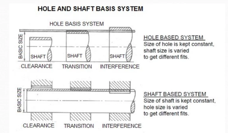
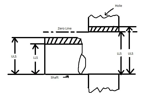
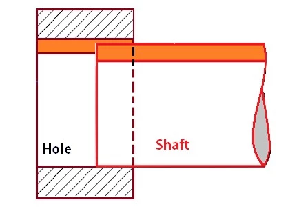
Fits are either shaft or hole-based. A hole is a component’s internal feature that is cylindrical or not, while a shaft is a component’s external feature that is cylindrical or not.
The hole’s size is kept constant for a hole-basis system while the shaft is altered to determine the fit. The reverse is for the shaft-basis systems where the shaft size is constant, and the hole size is altered to determine the fit.
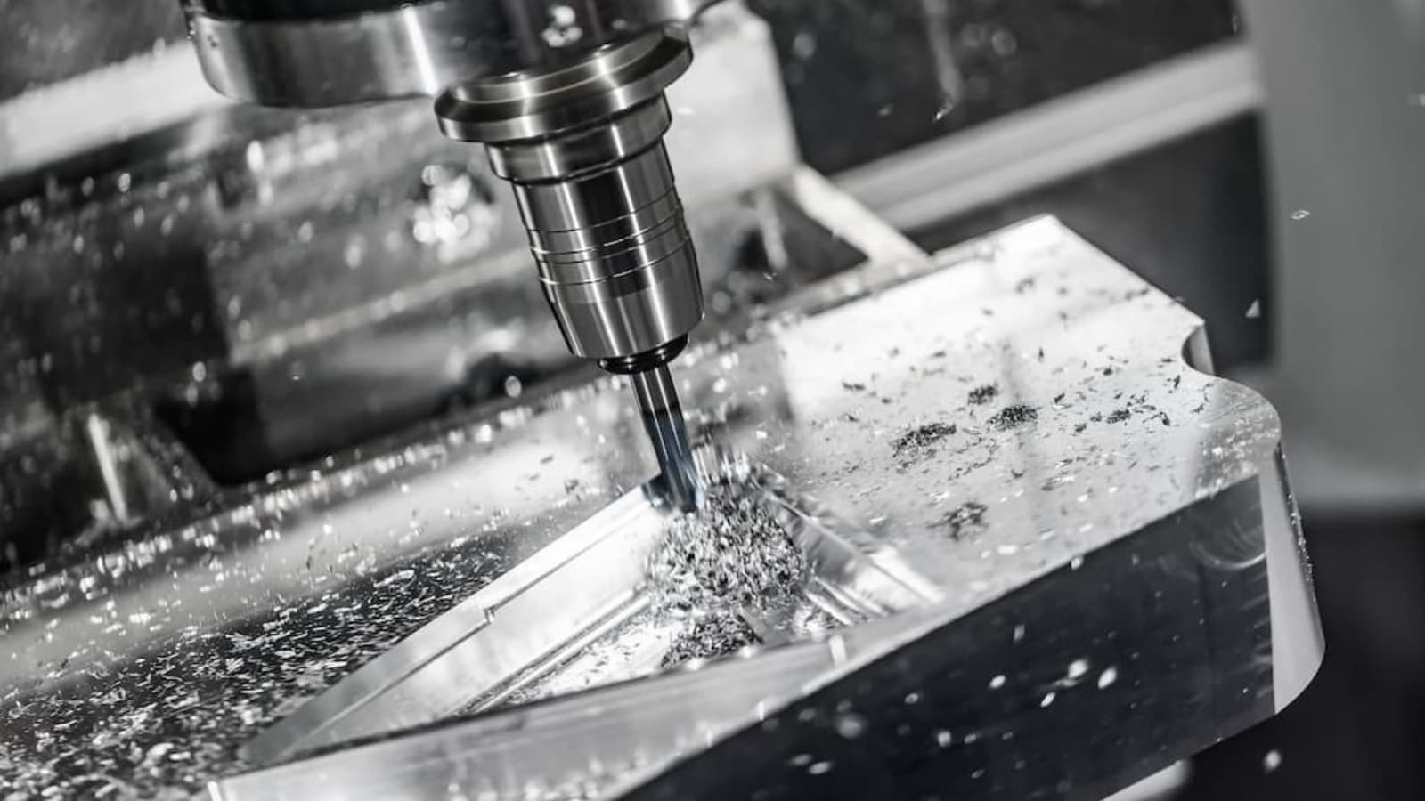
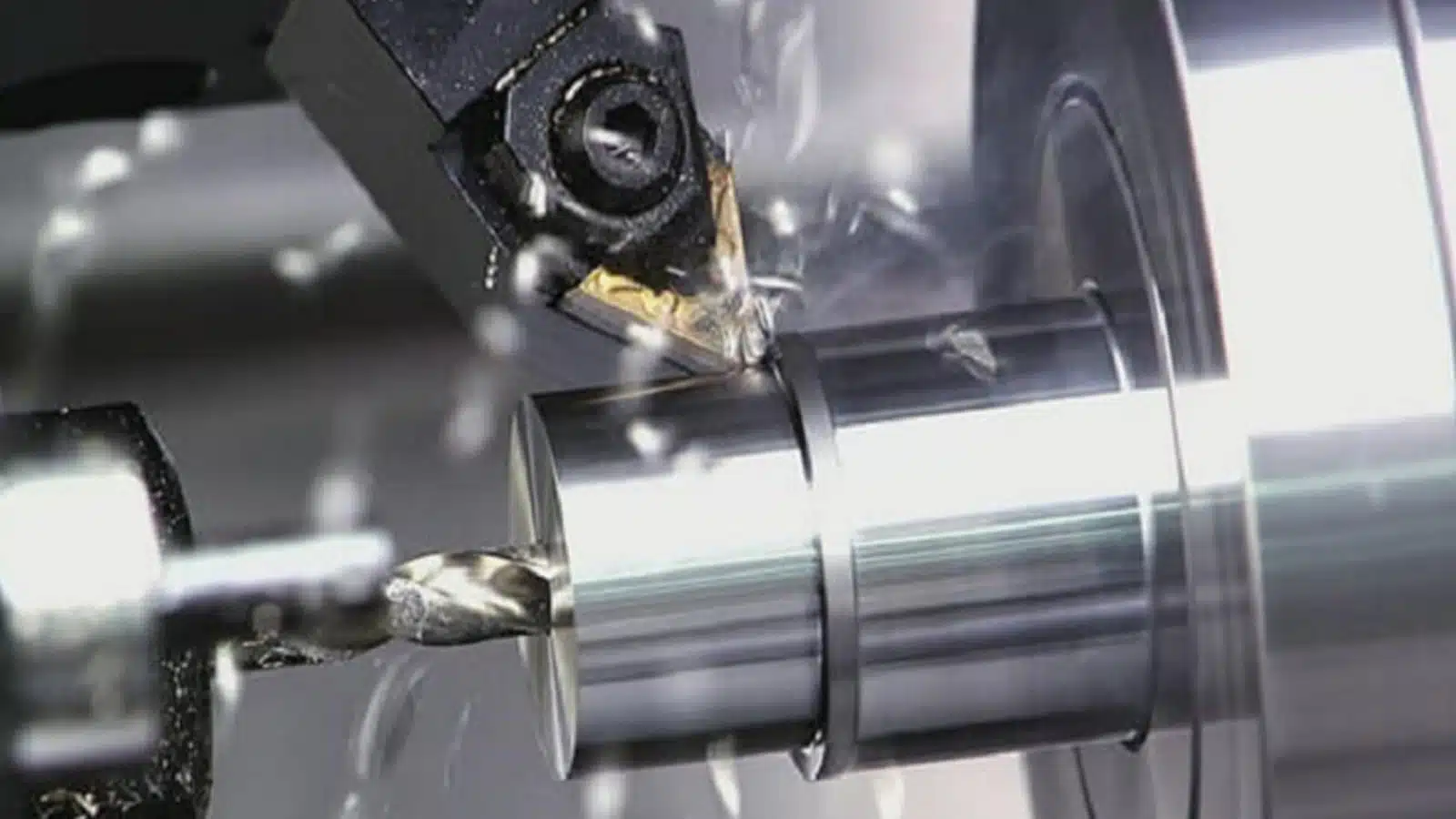
Note that CNC turning services is a precision machining method that can manufacture shafts with specific measurements, so this way makes it easier to get desired fits.
Fits and Tolerances
Fits and tolerances go together in determining the assemblage of the components of a product. Therefore, understanding both concepts will play a huge role in a successful assemblage. Tolerance is the difference between the max size and the mini size limit. It has a positive value and is represented by a number without a sign.
How to Name Different Fit Types in Mechanical Engineering
Understanding how they name the different types of fits is very important since it helps select the right types of fits for assembling a product.
According to the International Organization for Standardization, an alpha-numeric code names a particular fit and denotes the fit’s tolerance. The alphabet part of the code is for the hole or shaft.
A code with an upper-case letter is for the hole, while that of a lower-case letter is for the shaft. For example, based on the letter used, H7/h6 is a tolerance range for the hole (H7) and shaft (h6), respectively. This code will also allow engineers to identify the upper and lower size limit of the hole and shaft.
Types of Fits
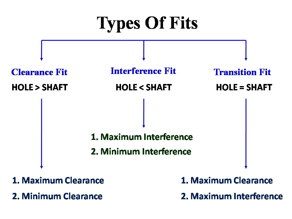
There are different fit types in mechanical engineering and each one is designed for different circumstances. According to ISO, there are three different types of fits used in manufacturing products.
Clearance Fits
From its name, a clearance fit is used in situations that call for loose mating and components’ free movement. Therefore, they are ideal for making products whose components need to slide in and out with ease.
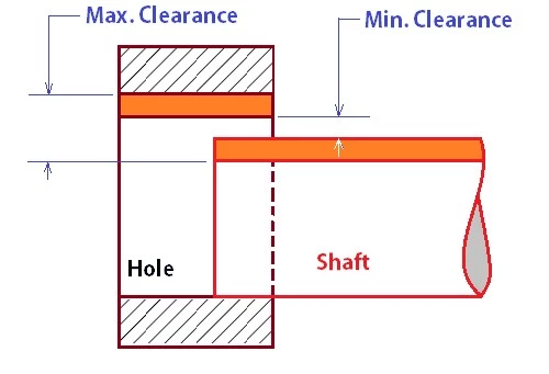
Clearance fits have a smaller shaft than the hole. This results in two conditions. One is a maximum clearance in which the shaft has the minimum diameter while the hole has its maximum diameter. The other is the minimum clearance in which the shaft is maxed, and the hole is minimum.
Clearance fits are further divided into five categories classified based on how loose they are. Below are the different types of fits under this category:
- Loose Running Fit
These are clearance fits with the largest clearance used in places where accuracy is not important
- Free Running Fit
These fits are for situations that require the movement of components with little consideration to accuracy.
- Close Running Fit
These fits are for situations that require small clearance about accuracy.
- Sliding Fit
These fits have high accuracy and are for situations that require high accuracy and small clearance. Therefore, parts where they are used can turn and slide freely.
- Locational Clearance Fit
Locational Clearance fits have high accuracy but can only provide minimal clearance.
Interference Fit
What’s an interference fit? It is also called a press fit or friction fit is a fastening of two components by pushing them together. The fastening occurs via many mechanisms, and it involves a substantial amount of force on the couple and uncouples the components. The mechanism also determines the different categories of interference to use.
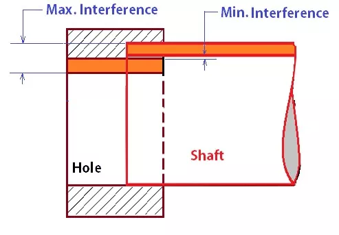
In interference fit, the difference between the shaft’s maximum size and the hole’s minimum size is the Maximum Interference. Also, the difference between the shaft’s minimum size and the hole’s maximum size is the Minimum Interference.
Interference fits have three categories:
- Press Fit
They have minimal interference as assembling is via cold pressing.
- Driving Fit
These fits have a more prominent interference fit than press-fit, and they need higher assembly force for cold pressing.
- Forced Fit
Assembling components requires heating the parts with a hole and freezing the shaft. Therefore, disassembling can lead to broken parts.
Transition Fit
These fits fall between clearance and interference fits and are ideal for situations in which accuracy is very important. For example, they are ideal for aligning where the mating component must be joined with extreme precision.
Engineers and machinists also call transition fits slip or push-fit. When you compare them in terms of the degree of clearance, they have a larger clearance than an interference fit. However, the clearance is not enough to guarantee movement in the joint. You can say that transition fits provide clearance or interference fit depending on the situation.
Transition fit has two major forms:
- Similar Fits
It leaves a small clearance or creates a small interference, and assembly is obtainable by using a rubber mallet.
- Fixed Fits
It leaves a small clearance or creates a small interference. Assembly is possible using light force.
How to Choose Suitable Fit for Your Projects
Choosing the right type of fit for your projects depends on understanding several factors. Below are the important factors that you should watch out for:
Application
Based on what you need, there are different types of fits ideal for different kinds of purposes. By going through properties such as accuracy and tolerance, exhibited by the different types of fits and the product’s proposed function, you should decide on the right fit for a project.
Budget
Before deciding on the right types of fits for your products, you should know your budget. For example, using fits with tighter tolerances will cost more than normal. Therefore, you must weigh your options carefully. It would be best to get a fit that delivers the right tolerance needed to perform its functions while reducing product development costs.
Tolerance
You must understand the concept of tolerance of a product to choose the right types of fits for such a product. You have to be specific about what you want. Also, you must answer questions such as whether you want the components to rotate in a full circle or want them to be tight.
Another thing you also need to be careful about is the tolerance slack, which is the total maximum or minimum tolerance of a particular measurement. For example, you have to be careful about the aggregation of different parts’ tolerance to make up a single product. This is very important if the resulting tolerance is very high.
Conclusion
Many things surround using the different fit types in mechanical engineering and employing each within different mechanical applications. By going through this article, you will have a perfect understanding of a fit and its different types. The article also showed what you need to look out for to choose the right fit for your projects. Understanding what a fit does is not as important as knowing how to apply it.
While this article will drill into the basic knowledge you can utilize in various design guides, you can also set your products apart by outsourcing to the right company. If you feel you need this, we at RapidDirect are in the best position to deliver quality and cost. With our engineering support, your product’s quality can shoot you over your competitors in no time.
FAQ
Therefore, a fit is used to describe the dimensional relationship between the components of a product. It is used to determine whether the components are loose or tight which is very important in various design guides.
There are different fit types in mechanical engineering, and each one is designed for different circumstances. According to ISO, the different types of fits in manufacturing products are Clearance fit, Transition fit, and Interference fit.