CNC machining is a versatile manufacturing process that can produce a wide range of parts with high precision and repeatability. It is an essential manufacturing process for producing high-precision, complex parts for various industries, including aerospace, automotive, healthcare, and electronics.
But here’s the twist: achieving perfection in CNC machining isn’t just about the machinery. It’s an art form, requiring a keen eye for design and a deep understanding of the process. In this guide, we unravel the secrets of CNC machining design. From general best practices to bespoke tips for different CNC operations, we’re diving into how to sculpt your designs for peak CNC performance. Welcome to the intersection of innovation and precision, where every guideline we share is a step toward manufacturing excellence.
What Is CNC Machining?
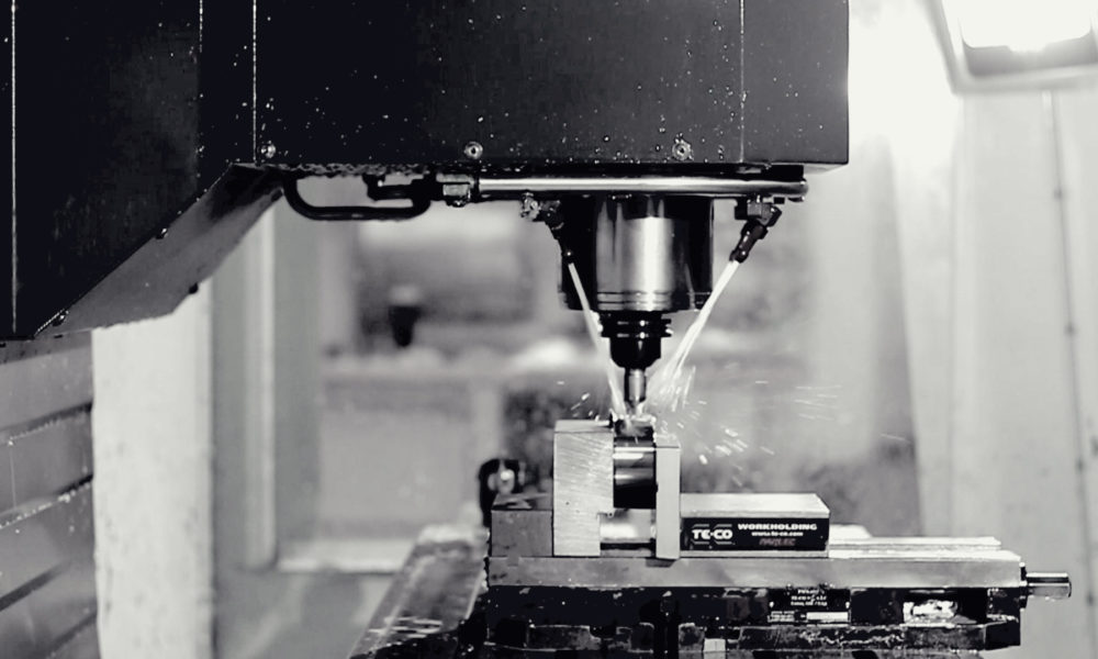
In CNC machining, a part’s development progresses from the initial concept to the physical form through a precise and technologically advanced process. Initially, a CNC designer creates the design using advanced CAD software. This design is subsequently converted into G-code, the directive code for CNC machines. Following this code, the CNC machine utilizes specialized cutting tools to methodically sculpt the part from a solid block.
CNC machines like vertical & horizontal milling and lathes can operate on various axes. To create relatively simple parts, traditional 3-axis machines can manipulate parts along three linear axes (X, Y, and Z). The 5-axis machining can work along the three linear axes and around two rotational axes to create more complex components.
The subjective manufacturing process allows the production of high-precision and complex parts in various materials like metals, plastics, and composites. Furthermore, it is fast, automated, precise, and scalable which makes it applicable in prototyping, one-off production, and large-scale production.
CNC Design Guidelines: Cost Reduction Tips
Understanding what CNC machining is sets the foundation for appreciating the importance of adhering to design practices. These practices are essential for reducing costs and maintaining a high standard of quality and precision.
Common Design Guides for CNC Machining
Avoid Non-Planar and Draft Angle Surfaces
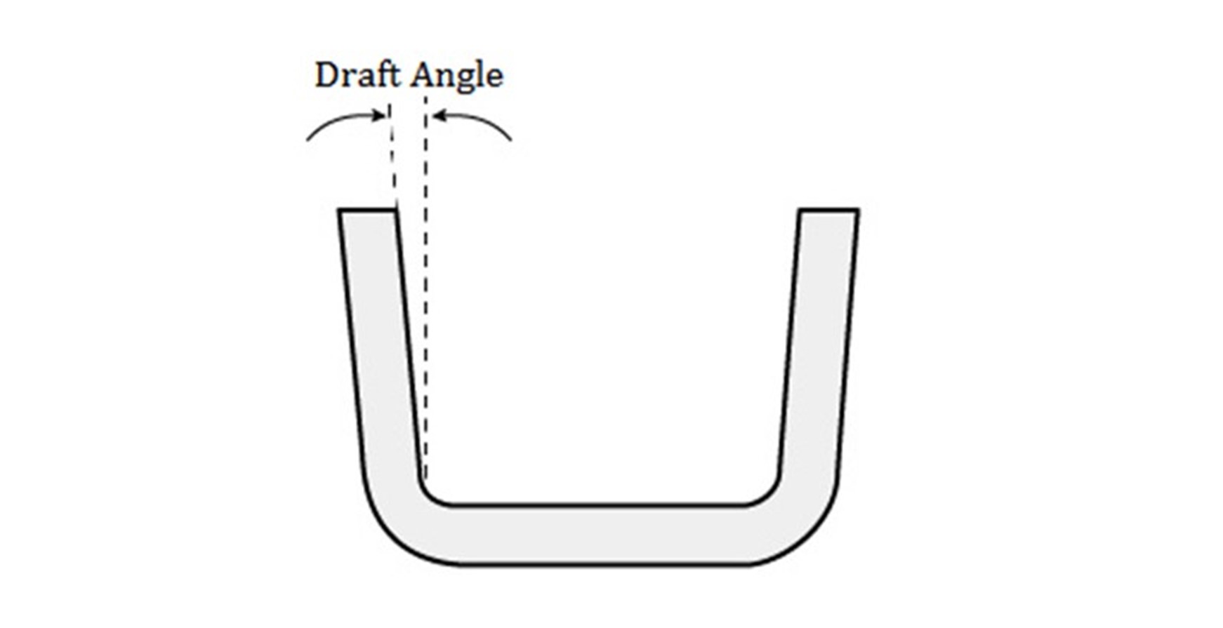
Non-planar and draft angle surfaces are complex and challenging to machine, which can result in slower cutting speeds, longer machining times, and increased tool wear. Additionally, these surfaces can make it more difficult to achieve consistent part quality and tight tolerance. To avoid non-planar and draft angle surfaces in your design:
- Use simple and flat geometry whenever possible.
- Use fillets and radii to soften sharp corners and reduce the number of complex surfaces.
- Incorporate draft angles into your design to allow easy material removal and reduce tool wear during machining.
Increase the Size of Internal Fillets
Internal fillets are rounded corners or transitions within a part that can reduce stress concentrations and improve the part’s strength. Increasing the size of these fillets will enhance the machining operation’s quality and efficiency by:
- Reducing cutting forces and tool wear during machining.
- Improving chip removal and material flow during cutting.
- Reducing the likelihood of tool breakage and premature tool wear.
- Improving surface finish and part quality.
Add Undercuts to Sharp Corners
Undercuts are recesses or notches in the corners of a part that allow for better tool access and improved material removal during machining. An optimized undercut design for CNC machining will:
- Reduce cutting forces and tool wear.
- Improve chip removal and material flow during cutting.
- Reduce the likelihood of tool breakage and premature tool wear.
- Improve the part’s surface finish and part quality.
However, creating undercuts can be a complex and challenging task because they can be difficult to reach using standard cutting tools. Furthermore, specialized tools or multi-axis machining may be required to machine undercuts. Minimizing the size and complexity of undercuts can help achieve better results. The following should be taken into consideration when designing undercuts:
| Recommended | |
| Undercut dimension | 3 mm to 40 mm |
| Undercut clearance | 4x depth |
Use Standard Tolerances
Standard tolerances ensure that finished CNC parts meet the desired specifications and functional requirements. Unnecessary tight tolerances can increase the cost and time of machining.
By specifying standard CNC machining tolerances, manufacturers can reduce the need for secondary operations and improve the overall efficiency of the machining process.
| Recommended | Feasible | |
| Tolerances | ±0.1 mm | ±0.02 mm |
Text and Lettering
When creating text or lettering, the tool must be able to maintain a constant width, height, and spacing throughout the machining process. Any variation in these factors can result in a final product that doesn’t meet design specifications.
You need to consider the font and size of the text or lettering. Texts that are too small may be difficult to read or they may not meet the desired specifications while texts that are too large may cause tool deflection or affect the accuracy and precision of the machining process. To address these challenges, some good design practices recommended by engineers and designers:
- Use standard fonts well-suited for the machining process
- Avoid overly complex or fine lettering
- Specify a larger font size
- Opt for a font with a more consistent width, height, and spacing
- Carefully consider the orientation of the text relative to the workpiece
- Adjust the tool accordingly to maintain a consistent height, spacing, and cutting speed.
Part Size
CNC machines have varying capabilities based on their size and capacity. Some machines may be too small to accommodate large parts, while others may not be able to handle parts that are too small. As a result, the parts to be designed should carefully consider the part size and choose the appropriate machine accordingly.
In addition to the size of the machine, the part size can also impact the speed of the machining process. Larger parts have a longer machining time and higher production costs because engineers need to remove more material during machining compared to smaller parts.
| Maximum Dimension | Minimum Dimension | |
| CNC Milling | 4000×1500×600 mm 157.5×59.1×23.6 in. | 4×4 mm 0.1×0.1 in. |
| CNC Turing | 200×500 mm 7.9×19.7 in. | 2×2 mm 0.079×0.079 in. |
Choose Softer Material
Softer materials are easier to machine, resulting in faster cutting speeds, reduced tool wear, and lower machining times and costs. Additionally, they are less prone to cracking or deformation during the machining process, which improves part quality and reduces post-machining processing time. Nevertheless, only choose a soft material if the intended use and final application of the product allow it.
Minimize Tool Changes and Workholding Setups
A higher need for tool changes and work holding setups during a machining cycle will lead to a time-consuming and expensive process. You can consider the following tips to minimize tool changes and setups:
- Parts with similar features and geometries can be CNC machined using a single cutting tool.
- Reduce the required setups by designing parts with consistent orientations or using modular fixtures that can accommodate multiple parts.
- Use multi-functional cutting tools that can perform multiple operations with a single tool change.
For CNC Milling Parts
Keep Available CNC Cutting Tools in Mind
Optimizing CNC parts for cost and lead time reduction involves aligning designs with the capabilities of standard CNC milling tools. By choosing designs that conform to the sizes and capabilities of these standard tools, the need for custom or specialty tools can be significantly minimized.
A practical example is the design of internal fillets. It’s advisable to avoid specifications that require a radius smaller than what standard CNC cutting tools can accommodate. Creating such features necessitates switching to smaller, possibly custom tools, which could lead to increased time and costs that may not justify the benefits. Therefore, staying within the limits of standard tool capabilities is a key consideration for efficient CNC part production.
Avoid Sharp Internal Corners
CNC milling has inherent limitations, one of which is the inability to create sharp internal corners. This limitation arises from the round shape of CNC milling tools. To navigate this, engineers often use radiused corners in their designs. The radius of these corners needs to be at least half the diameter of the milling cutter. For example, with a 1/4” cutter, the minimum radius for the fillets should be no less than 1/8”.
To address the challenge of sharp corner requirements in parts, specific design approaches are employed. These include:
- Drilling holes to “break” the corners.
- Allowing sharp edges to fit within the cavity.
- Using fillets when sloped or drafted surfaces meet vertical walls or sharp edges.
- Using square or ball end mills will always result in material between the wall and surface unless the surface is flat and normal to the tool.
Avoid Deep, Narrow Slots or Pockets
A good design practice is that the final depth of cut should not exceed certain ratios based on the material to be machined. For instance, with plastics, the ratio should not be greater than 15 times the diameter of the end mill, aluminum should be no more than 10 times, and steel’s limit is 5 times. This is because longer tools are more susceptible to deflection and vibration, leading to surface imperfections.
Furthermore, the internal fillet radius also depends on the diameter of the cutting tool. If a 0.55” wide slot for a steel part is to be CNC machined using a 0.5” end-mill, then the depth should not exceed 2.75”. Furthermore, high length-to-diameter ratio end mills can be harder to obtain. Hence, it is advisable to either decrease the depth of the slot or feature or increase the diameter of the cutting tool.
| Recommended | Feasible | |
| Cavity Depth | 4 times cavity width | 10 times the tool diameter or 25 cm |
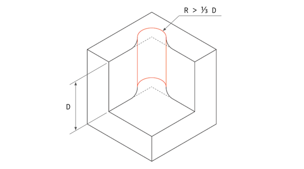
Design the Largest Allowable Internal Radii
The cutting tool size used in CNC mills should be considered during the design phase. A larger cutter removes more material in one pass, reducing machining time and costs.
To take full advantage of the capabilities of larger cutters, design your internal corners and fillets with the largest possible radius, preferably greater than 0.8mm.
An added tip is to make the fillets slightly bigger than the end-mill’s radius, such as a radius of 3.3mm instead of 3.175mm. This creates a smoother cutting path and produces a finer finish on your machined part.
| Recommended | |
| Internal Corner Radius | ⅓ times cavity depth (or larger) |
Choose Suitable Thickness
It is important to note that thin walls in parts can create significant challenges in the machining process, especially in terms of maintaining stiffness and accuracy of dimensions. To avoid these difficulties, you can design walls with a minimum thickness of 0.25mm for metal components and 0.50mm for plastic parts as they can withstand the rigors of the manufacturing process.
| Recommended | Feasible | |
| Wall Thickness | 1.5 mm (plastics), 0.8 mm (metals) | 1.0 mm (plastics), 0.5 mm (metals) |
For CNC Turning Parts
Avoid Sharp Internal Corners
Sharp internal and external corners in a part design can be a challenge during machining. To overcome this issue, it’s recommended to:
- Have radiused internal corners, providing a gradual transition for the tool to move smoothly.
- Incorporate a slight angle in the steep sidewalls to eliminate sharp internal corners.
- Simplify the machining process by reducing the number of operations required with a single tool.
Avoid Long, Thin Turned Parts
Instability is a common concern when it comes to long, thin-turned parts. The spinning part can easily chatter against the tool, creating an imperfect finish. To combat this, make use of the following CNC design tips.
- Incorporate a center drill at the end and use a center to keep the part spinning in a straight manner.
- Keep the length-to-diameter ratio at or below 8:1 to minimize the risk of instability during machining.
Avoid Thin Walls
During a CNC turning operation, be mindful of the amount of material being machined away. Over-machining can result in undue stress on the part, while thin walls can result in decreased stiffness and difficulty in maintaining tight tolerances.
As a guideline, the wall thickness of turned parts should be at a minimum of 0.02 inches to ensure stability and accuracy during the manufacturing process.
| Recommended | Feasible | |
| Wall Thickness | 1.5 mm (plastics), 0.8 mm (metals) | 1.0 mm (plastics), 0.5 mm (metals) |
For Drilling Parts
Optimal Hole Depth
The ideal depth of a drilled hole should balance the stability of the tool and the strength of the material being machined. Drilling too shallow can result in a weak joint and reduce the holding power of screws while drilling too deep can cause the drill bit to break or bend, leading to poor accuracy and surface finish.
To determine the optimal hole depth, you must consider the drill bit’s size, the material’s hardness and thickness, the strength required for the intended application, and the overall stability of the machine setup. Drilling the hole just deep enough to accommodate the screw or fastener is recommended, leaving some material for support. If a countersink is required, then the hole should be drilled deeper to allow for the countersink.
| Recommended | Feasible | |
| Hole Depth | 4 times the nominal diameter | 40 times the nominal diameter |
Distinguish Through Holes and Blind Holes
Understanding the difference between through holes and blind holes is important, as they both require different drilling techniques and tools.
A through hole is a hole that extends entirely through the workpiece from one end to the other. It is generally easier to produce, as the drill must enter and exit the part at opposite sides. Through holes are applicable in the fastening, mounting, and routing of electrical and mechanical components.
Blind holes, on the other hand, do not go all the way through the workpiece and stop at a specific depth. They are applicable in creating cavities, recesses, or pockets within the workpiece and are generally more challenging to produce than through holes. Blind holes require special CNC drill bits and cutting speeds to ensure that the cutting edge does not break through the bottom of the part.
| Through Holes | Blind Holes |
| Tip 1: Determine the correct drill size | Tip 1: It should be 25% longer than the needed depth |
| Tip 2: Maintain rigidity | Tip 2: Use a center drill |
| Tip 3: Use proper cutting fluids | Tip 3: Ensure sufficient hole depth above the drill tip |
| Tip 4: Monitor drill speed | Tip 4: Reduce speed and feed rates |
| Tip 5: Drill in stages | Tip 5: Avoid reaming |
Avoid Partial Holes
A partial hole occurs when the drill does not fully penetrate the material and can be caused by various factors such as the drill bit breaking, incorrect drill bit selection, or incorrect parameters such as speed, feed, and depth of cut. Therefore, you should select the right drill bit, maintain the right parameters, and use coolant to dissipate heat.
Avoid Drilling Through Cavities
While drilling, keep in mind that intersecting holes with existing cavities in parts can compromise its structural integrity. You can avoid this by positioning the drill points away from existing cavities. However, if the drilled hole must cross the cavity, a working practice is to make sure that its center axis does not intersect with it to maintain the part’s stability.
Design Standard Drill Size
Optimize your design for standard drill sizes to save time and money, and make it easier for machine shops to produce your part without needing costly custom tooling.
Consider using a standard drill size like 0.12” instead of a more precise but less common size like 0.123”. Also, try to limit the number of different drill sizes used in your CNC design, as multiple sizes increase the time and effort required for tool changes during the machining process.
| Recommended | Feasible | |
| Drill Size | Standard drill bit (0,12”) | Any diameter larger than 1 mm |
Specify Threaded Holes
A threaded hole allows for the attachment of bolts, screws, and other threaded fasteners. Make sure to specify the correct depth of the thread so that the threaded fastener has enough engagement to hold the part together. The deeper the thread, the stronger the fastener grip.
The type of material can affect the type of thread. On the one hand, soft materials may require a shallower thread. On the other hand, harder materials may need a deeper thread.
When specifying threaded holes in a drawing, use clear and accurate thread callouts to ensure the correct thread standard, pitch, and depth. Ensure enough clearance for the installation and removal of the threaded fastener without binding or stripping the thread.
| Recommended | Feasible | |
| Thread Length | 3 times the nominal diameter | 1.5 times the nominal diameter |
Avoid Deep Taps
Another crucial tip to achieve accurate and precise results is to avoid deep taps. The longer the tap, the greater the risk of it vibrating and wandering while in operation, leading to imperfections in the final product. A tap that exceeds 3 times its diameter is deep and can pose a significant challenge.
However, in many cases, even a tap that goes 1.5 times the diameter will provide ample thread engagement, thereby eliminating the need for a deep tap. Using deep taps increases the risk of tool breakage, flawed threads, and diminished precision, making it an undesirable aspect of CNC machining design.
| Recommended | Feasible | |
| Tap Size | 0.5 times the diameter | 1.5 times the diameter |
CNC Design Guide eBook
Dive into expert insights, detailed design tips, and practical strategies tailored for success.
Get your free download today and transform your designs for machining!
Limitations That Affect CNC Machining Design
When designing parts for CNC machining, it’s crucial to be mindful of certain limitations. Acknowledging these constraints is key to ensuring that the final product aligns with the required specifications while maintaining an efficient and cost-effective production process.
Tool Capabilities
A challenging aspect of the CNC machining process is the tool’s capability to reach and precisely machine features with a large depth-to-width ratio. The tool capabilities and access also play a significant role in determining the workpiece shape and the difficulty in reaching and machining intricate features.
For instance, deep cavities may require tools such as CNC threading tools or drilling tools with extended reach to reach the bottom. This can increase machine chatter and a reduction in accuracy. As a result, the tool’s size, shape, travel distance, and other factors contribute to the main design limitations of CNC machining and can impact the final product’s precision.
Tool Shape
Another thing you must consider is the cutting tool’s geometry as most cutting tools have a cylindrical shape and limited cutting length, which affects the final cut and its shapes.
For example, the internal corners of a workpiece will always have a radius, even if the cutting tool used is extremely small. This is because the tool’s geometry is transferred onto the machined part during material removal.
The cylindrical shape and restricted cutting length of common CNC cutting tools, such as end mill tools and drills, also limit their ability to machine certain features.
Tool Stiffness
In CNC machining, CNC machine and tool manufacturers make cutting tools using materials like carbide, tungsten, or similar materials with superior properties compared to the workpiece. Despite these materials’ high-performance characteristics, tool deflection can still occur and be a major source of deviation in the design and results.
While working with general tolerances may not present a problem, the slight deflection of the tool can become a significant issue in extremely precise jobs with tight tolerances. The deviation caused by tool deflection can restrict the design possibilities and compromise the accuracy of the final product.
Workpiece Stiffness
Cutting tools have exceptional stiffness and high-performance characteristics but may be unsuitable for some workpiece materials with superior mechanical properties.
The stiffness of the workpiece can result in vibrations and deflections that negatively impact the accuracy and precision of CNC machining operations. The precision and accuracy achievable with a stiff workpiece can vary, making it challenging to meet tight tolerances.
Workpiece Shape
The stability and success of CNC machining largely depend on the workpiece shape of the workpiece. The geometry of the workpiece is important because it determines the number of processes required and the overall viability of the design. In some cases, complex geometries may require reorientation during machining, even on multi-axis machines leading to the reduction in production efficiency.
Workholding
Stiffness is crucial in machining as it ensures smooth and accurate operations. A weak link in the “chain of stiffness” comprised of the machine, tool, part, and fixture can lead to vibrations and reduce precision.
Any part movement during machining leads to inconsistent results and deviates from the tolerances. A poor setup results in low accuracy and lacks precision, as each machined part will differ from the others.
Importance of CNC Design for Manufacturability
The design of a machined part is the foundation of the entire manufacturing process and is critical to the success of the finished product. Design for Manufacturability (DFM) helps to optimize the manufacturing process, making it faster, more efficient, and cost-effective. This often requires the modification of specific features that are not feasible to produce with the available equipment and materials.
Reduce Manufacturing Costs and Time
Part design plays a significant role in determining the efficiency and speed of the manufacturing process. By considering factors such as tool selection, cutting parameters, and machine capacity, manufacturers can optimize the production process for speed and efficiency. Furthermore, this can reduce cycle times, improve productivity, and reduce production costs.
Streamline Manufacturing Process Efficiently
The efficiency of CNC machining is directly influenced by the characteristics of the part being machined. When parts are configured to reduce tool wear and cycle times, they can enhance machine utilization, leading to greater productivity and profitability. In addition to DFM principles, there’s a focus on maximizing material utilization, which is a critical factor in cost reduction and profit increase.
Efficient material usage plays a significant role in reducing the overall cost of production. By carefully selecting appropriate materials and considering their properties like thickness and suitability for the intended geometry, manufacturers can achieve more effective material usage, thereby minimizing waste and optimizing production costs.
Avoid Fatal Design Flaws
Integrating CAD and CAM software in manufacturing processes offers significant design flexibility in modifying part specifications. This adaptability is crucial in accommodating rapid changes in customer demands or making adjustments to enhance performance, quality, or cost-efficiency.
Such flexibility allows for various process optimizations. For instance, manufacturers can streamline tool paths, decrease the number of setups needed, or enhance the efficiency of material use. Additionally, this approach facilitates greater automation in production, which can lead to a reduction in human errors and the necessity for repeated setups.
Material Selection Guide for CNC Machining
Material selection is an essential aspect of this CNC design guide as the CNC machining material’s properties will affect the machinability, cost, and overall quality of the finished part.
Metals
Metals are strong and durable materials suitable for making CNC machined parts that will be subject to high stress and heavy loads. Furthermore, they have good machinability, heat, and corrosion resistance, and are highly versatile in producing components for different applications.
Some of the common CNC metals include:
- Aluminum
- Steel
- Stainless steel
- Brass
- Copper
- Titanium
Plastics
Plastics are popular in CNC machining due to their cheapness, lightweightness, and moldability into complex shapes. Furthermore, some plastics such as PP(Polypropylene) and Polyetheretherketone (PEEK) are chemical resistant hence ideal for making parts with intended application in harsh chemicals or corrosive environments.
Some common CNC plastics are:
- Acetal (POM)
- Nylon
- Polycarbonate (PC)
- Acrylic (PMMA)
- Polyphenylene Oxide (PPO)
- Polyetheretherketone (PEEK)
- Polyethylene (PE)
Surface Finishes Selection for CNC Machining
Surface finishing on final products can affect their appearance, functionality, and durability. Common finishing options for CNC machined parts include:
As Machined
This is the raw surface finish that results from the CNC machining process. The surface of an as-machined part typically has a finish like 125 µin Ra, although tighter tolerances are achievable by requesting a finer finish of 63, 32, or even 16 µin Ra. As-machined surfaces may have visible tool marks, and the finish may not be uniform.
Bead Blasting
For a sleek, matte texture, bead blasting is a great option. This process involves propelling fine glass beads at the machined part’s surface in a controlled manner. The resulting finish is smooth and uniform. Different materials, such as sand, garnet, walnut shells, and metal beads, can be utilized depending on the desired outcome and the purpose of the bead blasting, whether it is for cleaning or as a pre-treatment for further surface finishing.
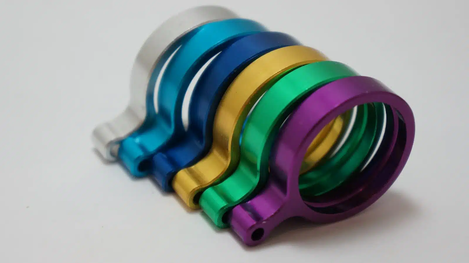
Anodizing (Type II or Type III)
Anodizing is a versatile and popular surface treatment for CNC machined components, offering superior resistance to corrosion, increased hardness, wear resistance, and improved heat dissipation.
It is applicable for painting and priming due to its high-quality finish. At RapidDirect, we offer two forms of anodization: Type II, known for its corrosion protection, and Type III, which provides an additional layer of wear resistance. You can also tailor both processes to produce a range of color finishes to suit your specific needs.
Powder Coating
The powder coating process is a highly effective way to protect machined parts from wear, corrosion, and elements. In this method, a special type of powdered paint is applied to the part’s surface, and then it is subjected to high heat in an oven. This process creates a long-lasting, protective coating with a multitude of color options to choose from. Whether you need a classic or bold look, powder coating provides a versatile and durable solution for your machined parts.
Custom
These surface treatments are tailored to meet specific design requirements and aesthetic preferences. These finishes can range from simple color changes to complex textured patterns. Custom finishes are essential for improving machined parts’ appearance, durability, and performance and can be important in creating a unique brand identity.
Turn Your CNC Design into Machined Parts in 3 Steps
Getting the best from CNC machining is possible with the right service and RapidDirect is your reliable CNC machining service provider committed to delivering exceptional results that meet international standards.
With ISO9001:2015 certification, our CNC machining services ensure high-quality parts that meet your specifications. In addition, our cutting-edge digital manufacturing platform offers a seamless experience for customers looking to get instant quotes for their CNC parts.
Our platform streamlines the design-to-production process and ensures that each part meets our customers’ specifications using automation and expert knowledge. We take pride in providing a comprehensive DfM experience that anticipates potential manufacturing challenges, ultimately delivering top-quality results in the shortest turnaround time possible.
Start your CNC machining project in just three simple steps:
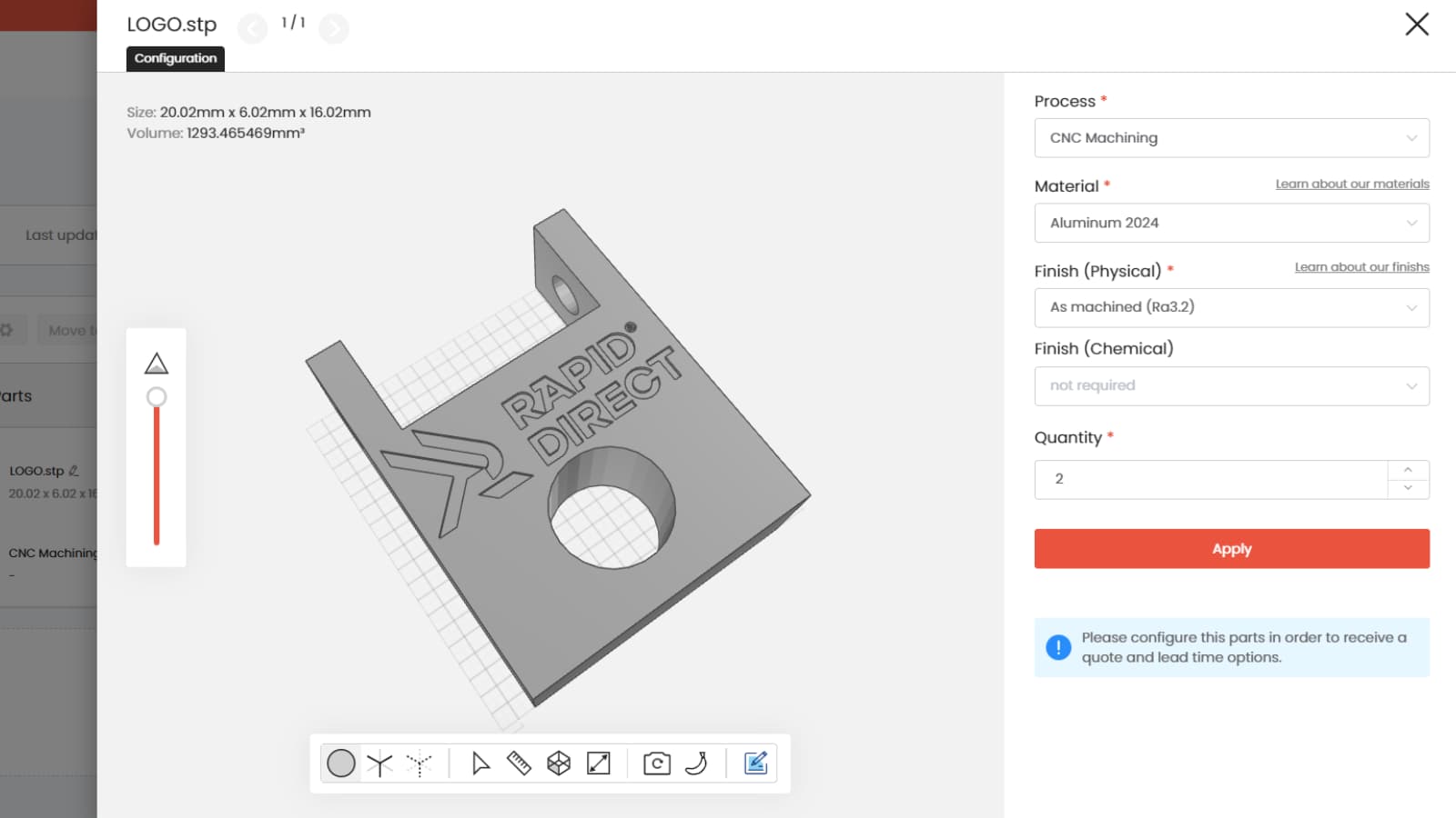
Upload Your Technical Drawing
The first step is to create a detailed technical drawing of your part. It should include all the critical dimensions, features, and surface finishes you need for your part. Then you can export the drawing to a CAD file format (STEP, STP, STL, IGES) using CAD software. You can then simply upload the CAD file on our online quotation platform.
Get Instant Quote
Our instant quotation platform lets you get a detailed price breakdown within a few minutes. It is simple, straightforward, and convenient. The instant quote also comes with a free, detailed DFM analysis report to help you improve your part’s design.
Start Manufacturing
Once you review to quote and confirm every design specification, our expert technicians will begin your CNC machining project to bring your idea to life. In our platform, you can track specdific production processes to get vital insight into your production efficiency.