CNC machining is one of the core processes in manufacturing that produce intricate and sophisticated products that have applications in various industries. At the heart of CNC machining’s unmatched efficiency and accuracy are the G and M codes – the critical programming languages that guide CNC machines.
Unlike common perception, G codes and M codes hold distinct roles in CNC operations. G codes primarily instruct the machine on the geometry of the cut, while M codes control the hardware aspects, like turning the spindle on or off. This nuanced difference is pivotal for understanding the full potential of CNC machining.
In this article, we delve into the specifics of these codes, unraveling their unique functions and how they synergize to optimize CNC machine performance.
What’s CNC Machining?
Understanding CNC machining is fundamental before delving into the specifics of CNC programming codes. CNC machining, or Computer Numerical Control machining, utilizes computerized controls and machine tools to produce precise and intricate parts from various materials. The technology has significantly transformed the landscape of modern manufacturing as it offers increased efficiency, and accuracy, and can create complex geometries.
Its key advantages are:
- Precision: CNC machining offers high precision and accuracy in producing complex parts.
- Efficiency: Automated processes and optimized tool paths contribute to efficient material removal.
- Versatility: Suitable for a wide range of materials and applications.
- Repeatability: CNC machines can produce identical parts with consistent quality.
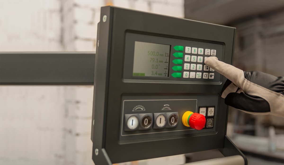
How Does CNC Programming Control CNC Machines?
Before the advent of computers, machinists used cards or tapes to control machine movements. They punched holes in these cards in a specific order to create the codes. While this was also effective at the time, it was quite tedious. Also, these cards were prone to damage or getting lost in the machine shops. This led to several problems in production at the time.
When machinists started using computers for numerically controlled machines, they still came across a few problems. This was because they had to input the codes manually. This would, of course, be very tedious when they were making quite sophisticated parts that required a lot of instructions.
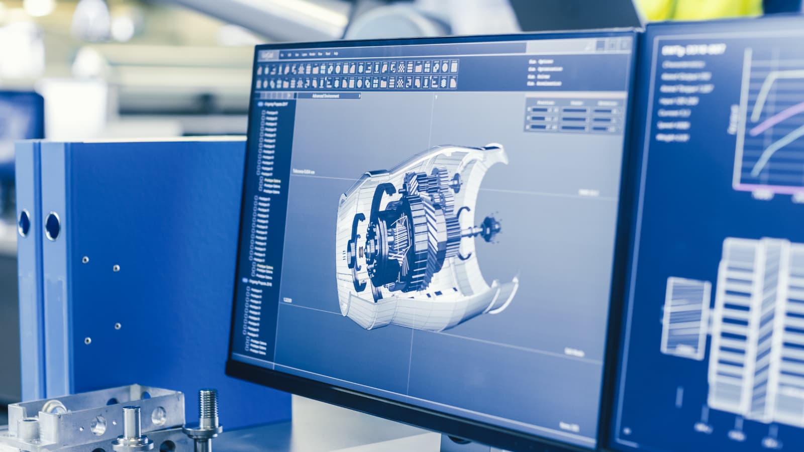
The advent of advanced computers and software has revolutionized CNC machining. Machinists now simply input instructions into software, which then generates the necessary G codes and M codes for the machines. This process, greatly simplified by CAD and CAM software, has made code generation and machine operation more efficient and accessible, enhancing both precision and complexity in manufacturing.
To start the process, the programmer needs high-level computer-aided software. The programmer then imports the machine model and the machining fixture into the software, then selects the tools and the tooling paths of the spindle. Once these parameters are set, the software efficiently generates the requisite G and M codes, which are essential for the CNC machine to operate effectively.
What Are G-Codes in CNC Programming?
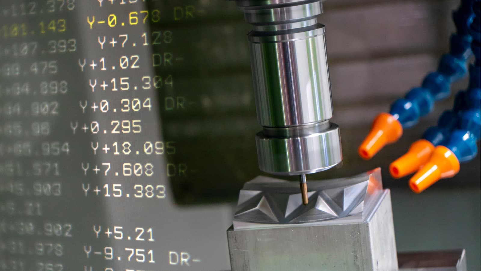
G code (also RS-274D) is the most popular CNC programming language. Most G code commands are in alphanumeric format and start with G which stands for geometry. They are responsible for the movements of CNC machines, telling the machine where to start, how to move, and when to stop when fabricating a part.
However, G code can be quite complicated for machinists because different machines read G codes in different formats. Most machines’ differences are in the presence or absence of spaces between commands and the number of zeros between the letter and number in the commands. For example, a machine might use G3 while another uses G03. Machinists must always be conversant with the type of machine they’re using. Otherwise, errors in the command can lead to serious problems in parts production.
Beyond G codes, programmers use other letters that signify distinct functions as well. These letters diversify the language of CNC programming, enabling a wide range of commands for precise and intricate machining tasks.
- A: It directs the tool around the x-axis.
- R: It gives the radius of the arcs the machine makes.
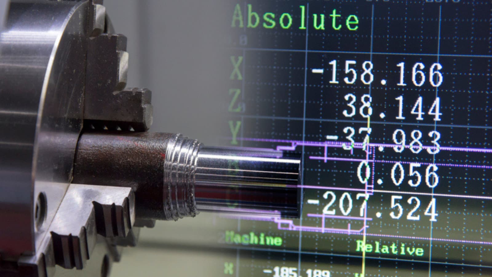
- X, Y, Z: These three values indicate the tools’ position in three dimensions – X and Y represent the horizontal and vertical dimensions, respectively, while Z represents the depth.
- I and J: Both values designate the incremental center of any arc the machine makes.
- N: N gives the line number.
The code also uses other letters which depend on the machine’s capabilities.
| Block | Description | Purpose |
| % | Start of program | Start Program |
| O00001 (Project 1) | Program number (Program Name) | Start Program |
| (T1 0.25 END MILL) | Tool description for operator | Start Program |
| N1 G17 G20 G40 G49 G80 G90 | Safety block to ensure the machine is in safe mode | Start Program |
| N2 T1 M6 | Load Tool #1 | Change Tool |
| N3 S9200 M3 | Spindle Speed 9200 RPM, On CW | Change Tool |
| N4 G54 | Use fixture Offset #1 | Move to Position |
| N5 M8 | Coolant on | Move to Position |
| N6 GOO X-0.025 Y-0.275 | Rapid above part | Move to Position |
| N7 G43 Z1. H1 | Rapid to the safe plane, use tool length Offset #1 | Move to Position |
| N8 ZO.1 | Rapid to feed plane | Move to Position |
| N9 G01 Z-0.1 F18 | Line move to cutting depth at 18 IPM | Move to Position |
| N10 G41 Y0.1 D1 F36 | CDC left Lead in Line, Dia. Offset #1, 36 IPM | Machine Contour |
| N11 Y2.025 | Line Move | Machine Contour |
| N12 X2.025 | Line Move | Machine Contour |
| N13 Y-0.025 | Line Move | Machine Contour |
| N14 X-0.025 | Line Move | Machine Contour |
| N15 G40 X-0.4 | Turn CDC off with lead-out move | Machine Contour |
| N16 G00 Z1 | Rapid to safe plane | Machine Contour |
| N17 MS | Spindle Off | Change Tool |
| N18 M9 | Coolant Off | Change Tool |
| (T2 0.25 DRILL) | Tool description for operator | Change Tool |
| N19 T2 M6 | Load Tool #2 | Change Tool |
| N20 S3820 M3 | Spindle Speed 3820 RPM, On CW | Change Tool |
| N21 M8 | Coolant On | Move to Position |
| N22 X1 Y1 | Rapid above hole | Move to Position |
| N23 G43 Z1 H2 | Rapid to safe plane, use tool length, Offset 2 | Move to Position |
| N24 Z0.25 | Rapid to feed plane | Move to Position |
| N25 G98 G81 Z-0.325 RO.1 F12 | Drill hole (canned) cycle. Depth Z-.325, F12 | Drill Hole |
| N26 G80 | Cancel drill cycle | Drill Hole |
| N27 Z1 | Rapid to safe plane | Drill Hole |
| N28 MS | Spindle Off | End Program |
| N29 M9 | Coolant Off | End Program |
| N30 G91 G28 Z0 | Return to Machine Home Position in Z | End Program |
| N31 G91 G28 X0 Y0 | Return to Machine Home Position in XY | End Program |
| N32 G90 | Reset to absolute positioning mode (for safety) | End Program |
| N33 M30 | Reset the program to the beginning | End Program |
| % | End Program | End Program |
What Are M-Codes in CNC Programming?
M code, akin to G code, commences with the letter ‘M’ and encompasses a series of auxiliary commands vital for controlling a CNC machine’s non-geometric functions. These codes, often referred to as miscellaneous codes, manage essential operations like halting the program, activating coolant systems, and powering down the machine post-operation.
In CNC programming, it is crucial to use M codes with precision. Typically, each block of program information should contain only one M code. This practice is imperative because M codes often serve to activate or deactivate various machine functions. Overlapping these commands within a single block can lead to programming conflicts and operational errors.
Similar to G codes, M codes vary across different CNC machines. This variance can include differences in the numerical formatting of the codes, such as the inclusion or exclusion of leading zeros. For instance, one machine might recognize an M code as ‘M3’, while another requires ‘M03’. Therefore, machinists must be well-versed in the specific coding requirements of the equipment they operate to ensure seamless and error-free machining processes.
A List of G and M Codes for CNC Machining
This section illustrates a range of basic G and M codes, highlighting their distinct functionalities. While some codes have similar meanings across both lists, others differ significantly in application and interpretation in CNC machining.
Commonly Used of G Codes
G-codes in CNC machining transform complex operations into methodical tasks, with standardized codes ensuring consistency and peak performance. Here’s a look at some key G-Codes crucial for anyone working with CNC machines.
- G00 – Rapid Positioning: This command is used for swiftly moving the tool to specified coordinates at maximum speed. Primarily, it positions the tool without engaging in material cutting, optimizing the machine’s efficiency for non-cutting movements.
- G01 – Linear Interpolation: This command directs the tool to move in a straight line between two points at a set feed rate. Predominantly utilized for straight-line cutting, G01 is one of the most frequently used G codes in CNC machining.
- G02 – Circular Interpolation (Clockwise): This command facilitates the creation of arcs and circles by guiding the tool along a circular path in a clockwise direction. It ensures precise movement to a specified endpoint, essential for circular machining tasks.
- G03 – Circular Interpolation (Counter-Clockwise): This command mirrors G02, but with the tool moving along a circular path in a counter-clockwise direction. It’s essential for crafting arcs and circles that require a counter-clockwise approach.
- G04 – Dwell: This command instructs the CNC machine to temporarily pause at its current position for a predefined period. The dwell function is particularly useful in scenarios such as allowing a cutting tool to cool down or enabling the spindle to attain the desired speed.
A List of Other Function G Codes
| Code | Category | Function | Modal | For Turning or Milling |
| G17 | Plane Selection | XY Plane Selection | Yes | Both |
| G96 | Speeds and Feeds | Constant Surface Speed | Yes | Turning |
| G91 | Positioning and Modes | Incremental Mode | Yes | Both |
| G03 | Circular Interpolation (CCW) | Create arcs and circles (Counter-Clockwise) | Yes | Both |
| G04 | Dwell | Pause for a specified duration | No | Both |
| G18 | Plane Selection | XZ Plane Selection | Yes | Turning |
| G19 | Plane Selection | YZ Plane Selection | Yes | Turning |
| G20 | Unit System | Inch System | Yes | Both |
| G21 | Unit System | Metric System | Yes | Both |
| G40 | Cutter Compensation | Cancel Cutter Compensation | Yes | Milling |
For additional information on G codes, please refer to this resource.
Commonly Used M Codes
Although CNC machines typically use M-codes akin to G-codes, standardization across models isn’t universally adopted. Thus, CNC programmers must be cautious about machine-specific codes. Yet, certain M-codes consistently retain the same meaning across all machines.
- M00 – Program Stop: To stop the CNC program temporarily. It often requires operator intervention to resume the program.
- M02 – Program End: To end the CNC program. After executing this code, the control will stop, and the operator may need to reset or restart the machine.
- M03 – Spindle On, clockwise: To start the spindle rotation in the clockwise direction. It is often followed by a speed command (S) to set the spindle speed.
- M04 – Spindle On, Counterclockwise: Similar to M03, M04 is used to start the spindle, but it rotates in the counterclockwise direction.
- M05 – Spindle Stop: To stop the spindle rotation. It is often employed when a tool change or other operation requires the spindle to be stationary.
A List of Other Function M Codes
| Code | Category | Function | Modal | For Turning or Milling |
| M08 | Coolant | Coolant flood or on | No | Both |
| M42 | Auxiliary Functions | High Gear Select | No | Turning |
| M19 | Spindle Control | Change spindle orientations | No | Milling |
| M00 | Program Control | Program Stop | No | Both |
| M02 | Program Control | Program End | No | Both |
| M03 | Spindle Control | Spindle On, Clockwise | No | Both |
| M04 | Spindle Control | Spindle On, Counterclockwise | No | Both |
| M05 | Spindle Control | Spindle Stop | No | Both |
| M06 | Tool Change | Tool Change | No | Both |
| M09 | Coolant | Coolant Off | No | Both |
For additional information on M codes, please refer to this resource.
Let’s Summarize The Difference Between G and M Codes
G-codes:
- Direct the motion and function of the CNC machine.
- Describe positions and movements, such as rapid positioning to a specific XY plane, linear feed movement, and circular interpolation.
- Related to geometric codes, serve in product design.
- Activate the CNC machine.
M-codes:
- Control operations not involving movements, such as stopping programs, changing tools, turning the spindle on or off, and activating coolant systems.
- Relate to machine functions and serve in various miscellaneous operations.
- Activate the machine’s programmable logic controller (PLC).
RapidDirect’s Expertise in CNC Machining
Explore CNC machining solutions with RapidDirect, where understanding and precision meet. Our team is skilled in the intricacies of G and M codes, ensuring that every project is handled with attention to detail and expertise. We believe in offering high-quality results that are both effective and affordable.
Our user-friendly platform streamlines your experience, offering instant quotations and a straightforward project tracking process. Managing your CNC machining needs becomes effortless with our efficient and accessible system.
Let’s collaborate to achieve your manufacturing goals.
Conclusion
Using CNC machines is one of the most important processes in CNC machining. However, these machines cannot function without G codes and M codes which instruct them on what to do. Understanding how to generate these codes is vital to the CNC machining process and successful parts production. Mastery of these codes gives you a head start in your CNC programming career.