Gears, a crucial part of engines, are mechanical devices that permit a change in the torque and speed of machines. There are different types of gears with specific requirements and specifications, ranging from simple forms to more complex ones.
Frequently, a number of gears form complex machines, but that is not always the case. For example, gears are present in simple machines like clocks, where they regulate the speed of the clock’s hand. In this article, we will discuss different mechanical gears and their applications. Let’s read on.
What are Gears?
Gears are rotating mechanical devices with teeth that enable torque and speed transmission. Often, mechanical gears are cylindrical with sets of teeth around the body. When two or more gears work in sync, they are in transmission. The power transmission is what leads to a change in speed or torque.
Advantages of Gears
- Gears are strong mechanically. Hence, they can lift higher loads.
- With the aid of a gearbox, they permit a change in velocity ratios.
- They work well at low velocities.
- High-efficiency power transmission.
- They are ideal for high torques value transmission.
- Gears require only routine lubrication, consequently, little focus on maintenance.
- They are highly durable, so the gear system serves for a long time.
Disadvantages of Gears
- Gears are not suitable for long-distance motion transmission.
- They are not flexible.
- Gears are noisy, especially at high speeds.
- They are not suitable when shafts are distant.
Different Types of Gears and Their Applications
In mechanics, grouping gears into various classes depends on teeth configuration, use and direction of motion. Below are the most important kinds of gears.
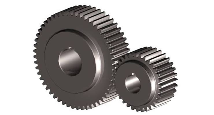
Spur Gear
Spurs gears transmit power in the same plane when the two shafts (the driving and the driven) are parallel. The teeth of spur gears are parallel to the shaft axis. Therefore, when it meshes with another spur gear, it transmits the power in a parallel shaft. They are the commonest forms of gears that have applications in automotive, conveyor systems, gear pumps and motors, speed reducers, etc.
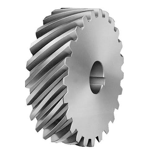
Helical Gear
Helical gears have their teeth positioned at an angle to the shaft in contrast to spur gears which are parallel. They have multiple teeth in contact during transmission. As a result, helical mechanical gears can carry larger loads. Also, they work with less noise and vibrations as loads are better distributed. In addition, they experience less wear and tear conditions since there is less friction. Different helical gear types will be shown below.
Single or Double Helical Gear
Single helical gears have teeth in either the left-hand helix or right-hand helix. However, the double helix gears have teeth in both directions. In double helical gears, there are two helical faces next to each other with a space between them. The faces are identical but have opposite helical angles. Using a double helical gear ensures more significant tooth overlap, which results in smoother transmission.
Herringbone Gear
This set of quite similar to the double helical gear. However, they are smaller and have no space between the two helical faces. Herringbone gears have the two helical gears joined side to side. They are not so common because of high production costs and manufacturing difficulties, although they are better suited for vibration and high shock applications.
Screw Gear
Screw gears are a pair of helical gears operating at a twist angle of 45 degrees. They occur on non-parallel and non-intersecting shafts. They have a low load carriage capacity because of the single tooth contact. Therefore, these gears are not ideal for transmitting large power.
Applications of Helical Gears
- Water pumps
- Mixers
- Automobiles
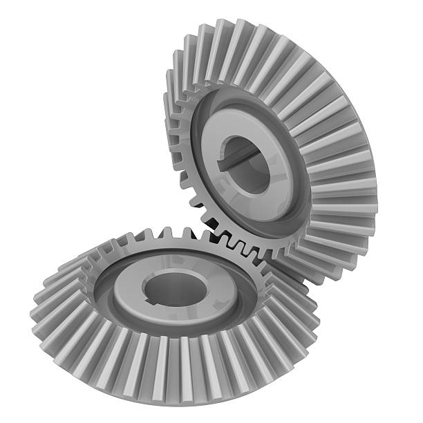
Bevel Gear
Bevel gears are cone-shaped, with teeth around the cone. They transmit force between perpendicular shafts. That is shafts that intersect at a right angle (90 degrees). However, bevel gears are expensive and do not transmit large torque per size like parallel shaft configuration.
Straight Bevel Gears
Straight bevel gears are the most common configurations of the bevel gear tooth. The reason for this is the design’s simplicity and ease of manufacturing. Straight bevel teeth engage together all at once rather than gradually when properly matched. The pitch surface of straight bevel gear types is conical with straight teeth that tapers toward the tip.
Spiral Bevel Gears
Spiral bevel mechanical gears have curved tooth lines, and they have a better tooth contact ratio than the straight bevel gear. Hence, they are superior in efficiency and strength and produce less vibration and noise. However, they have manufacturing difficulties.
Zerol® Bevel Gears
Zerol® bevel gears are a registered trademark of Gleason Co. The gear adopts features of both straight and spiral bevel gears with curve teeth. Therefore, the gear is suitable for both applications. However, they have zero twisting angles, and hence, teeth can rotate in either direction.
Miter Gears
Miter gears are a special type of bevel gear in that they have the same number of teeth. They have their shafts positioned at 90 degrees to each other, and these gears change power transmission without affecting speed. Miter gears are unique because they have a gear ratio of 1. In contrast, other bevel gears can have ratios ranging from 10:1 to 500:1.
Crown Gears
Crown gears, which are sometimes called face gears, also have their teeth at right angles to the face of the wheel. They have a pitch cone of 90 degrees. In industries, crown gears mesh with other bevel gears or spur gears in power circular motion.
Hypoid Gears
Hypoid gears appear similar to spiral bevel gears, but they function in non-intersecting shafts. They operate at 90 degrees and are common in automobile sectors. You see these gears on vehicle axles.
Applications of Bevel Gears
- Mixers
- Watering systems
- Crushers
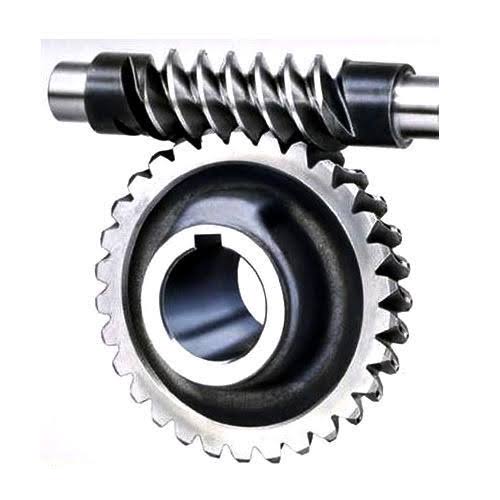
Worm Gear
Worm gear consists of a screw-shaped cut on the shaft (worm) and the mating gear (worm wheel). This gear type transmits the power in non-intersecting shafts that make right angles. The types of gears work by making sliding contact with less friction, rather a smooth and quiet rotation. So, they are suitable for high shock applications. However, they have a low efficiency, which restricts their use to low-power applications.
Applications of Worm Gears
- Farm machines
- Small conveyors
- Packing equipments
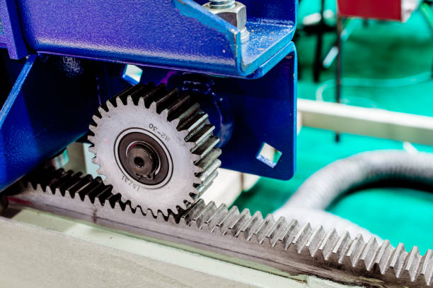
Rack and Pinion Gear
Rack and pinion gear often occur in pairs. They consist of two circular gears: the pinion engaging a linear gear – the rack. They translate rotatory motion into linear. These gears are common in the steering system of automobiles. Rack and pinion gear systems can use either straight or helical gears. The primary application of rack and pinion gears is in automotive steering.
Have needs to machine gears? RapidDirect is your best partner for gear machining. Get your quotation today!
A Brief Table of Different Types of Mechanical Gears
| Types of Gears | Characteristics | Applications |
| Spur gear | a. The commonest form of gear. b. Easy to manufacture. c. Use for parallel axes gear configuration. d. Circular gear body. | a. Clocks b. Small conveyors c. Automotive |
| Helical gear | a. Circular gear body. b. Efficiency is lower than spur gears. c. Parallel axes configuration.Smoother operation with less noise. | a. Water pumps b. Mixers c. Automobiles |
| Bevel Gear | a. Conical gear body. b. Intersecting axes configuration. c. Straight, spiral and Zerol® bevel designs exist. | a. Mixers b. Watering systems c. Crushers |
| Worm Gear | a. Gear pair consists of circular and screw gears. b. Low efficiency. c. Non-parallel and non-intersecting configurations. | a. Farm machines b. Small conveyors |
| Rack and pinion gear | a. The gear pair consists of a gear rack and a cylindrical gear. b. Parallel axes configuration. c. Changes rotatory motion to linear motion and vice versa. | a. Automotive steering b. Weighing scale |
Basic Parameters for Gear Design
Below, we will discuss basic gear parameters that affect gear designs.
Gear Shape
Most gears are circular, with teeth aligned around the cylindrical body. However, they also occur in conical, elliptical, square and triangular forms. Circular gear systems have a constant gear ratio for rotary speed and torque. Therefore, similar input produces the same speed and torque output. The opposite is what exists in non-circular gear types. Consequently, they can perform special irregular motions requirements, such as changing speed and reverse motion.
Module
Module refers to the size of a gear tooth in millimeters. Therefore, the module directly relates to the size of the gear teeth. It is an important parameter to look out for in gearing. The module is the value obtained from dividing the pitch diameter by the number of teeth in gear. Mathematically, we have it as:
Module = Pitch diameter / Number of teeth.
However, there are common values for modules, which follow the way they occur in industrial applications.
Gear Axes Configuration
Gear axes configurations are in three forms: parallel, intersecting, and non-parallel (or non-intersecting). Gears with parallel axes occur parallel with shafts rotating in opposite directions. Intersecting gears intersect on the same plane, while the non-parallel gears have their axes cut across different planes. However, intersecting and parallel gear configurations have greater efficiency and speed than non-parallel gears.
Pressure Angle
Pressure angle is the angle the tooth forms with the normal to the pitch line. As a rule, a pressure angle of 20 degrees is often used. Although, angles of 14.5 and 17.5 exist in some instances. Larger pressure angles indicate a wide dedendum which results in greater tooth strength.
Number of Teeth
The number of teeth and the values of module and pressure angle are crucial in calculating the dimensions of gears. The number of teeth is vital in calculating the gear speed (gear ratio) using the expression below:
A number of teeth of input gear / Number of teeth of the output gear.
Twist Direction
A gear is right-handed when it has its teeth to the right and left-handed when they are to the left. For power transmission to occur in a pair of helical or bevel gears, the two gears working hand in hand must have opposite twist directions. For example, two helical gears with teeth moving in the same direction will never mesh. However, screw and worm gears are unidirectional yet mesh.
Torsion Angle
Torsion angle is the angle of inclination of the tooth relative to the cylinder’s axis. Increasing the torsion angle of gears leads to a more significant thrust direction. As a result, there is a drop in the machine’s efficiency. Generally, torsion angles less than 25 degrees are ideal for helical gears to reduce the thrust.
Considerations When Designing and Selecting Gears
Below are some critical factors to consider when designing and selecting gears.
Operational and Environmental Conditions
The operational and environmental conditions of gears are critical for their durability and performance. Operating conditions include stress and friction placed on teeth. On the other hand, environmental conditions include humidity, temperature, and cleanliness. The two conditions affect gear type and design factors such as construction, surface treatment, lubricants and lubrication method.
Dimensional Restrictions
Dimensional restrictions are limitations to the space occupied by gears. For instance, gears should be at the center between shafts. However, there are cases where they are a little further from the center to fit the gear system better. In such cases, the teeth profile is changed. Using specific gear and designs that best suit the space is another effective means of managing dimensional limitations.
Transmission Requirements
Mechanical gears often transfer motion and torque within the machine components. Though, based on the design and construction, they may change the direction of motion and increase speed or torque output. When designing gears, the specification and application requirements: directional changes or increase in speed or torque are factors to consider. They may influence the gear type, design and configuration.
Design Standards
Gears have various specifications, with no general industry standard. Frequently, gear designs either suit the manufacturer’s standard or design specifications of the machine or system. However, several countries have created a standard to serve their industries. For instance, in the United States, gears are grouped by American Gear Manufacturers Association (AGMA). Japan and Germany, too, have such associations.
Costs
Cost is a factor, especially when dealing with customized gears. The design materials, construction, surface finishes, precision and lubrication requirements affect cost. While it is necessary to go with gears that meet all specifications, the cost must be factored. So, where regular gears meet up to standard, it is better to go with them, as customized gears will attract other expenses.
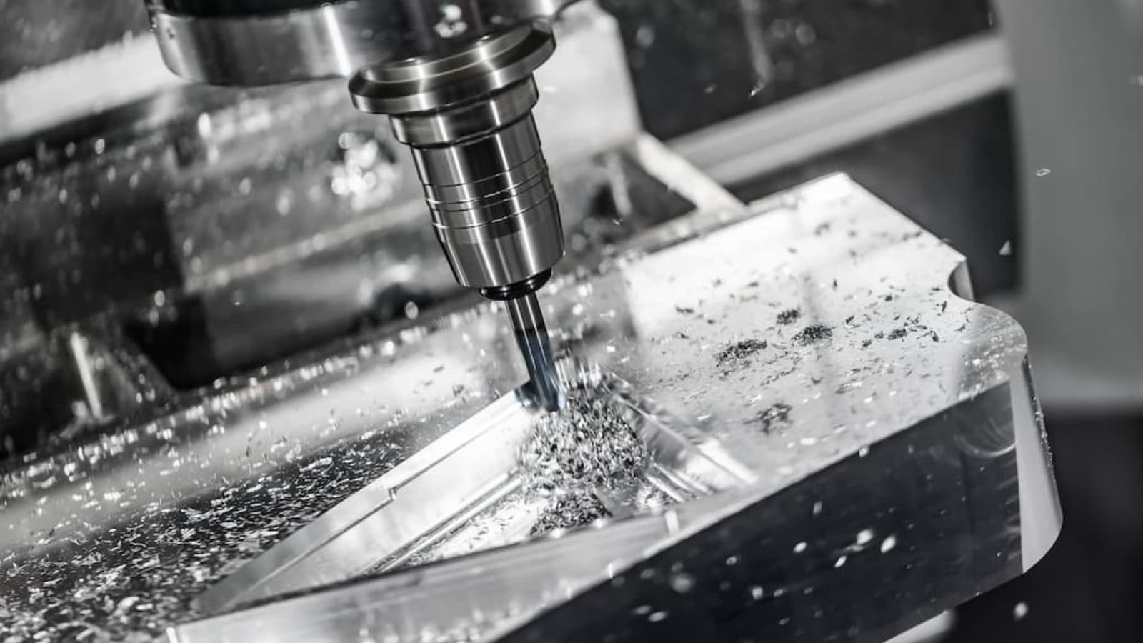
How to Produce Gears
Gears are produced using several gear manufacturing processes. Some of which include:
- Forging
- Extrusion and cold-drawing
- Powder metallurgy
- Blanking
- Gear Machining
Machining is often done to achieve the gear’s final shape and dimension. Once the gears are produced, surface finishes, such as grinding and honing, can then be applied to improve the general feature of the gear.
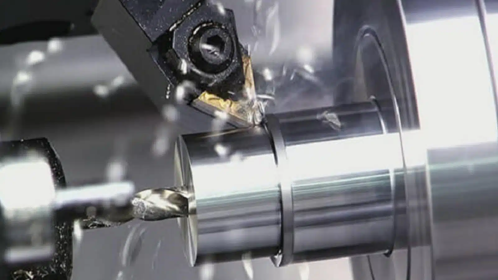
RapidDirect – Gear Machining Services
Reading through this article, you must have amassed a vast knowledge about gears, their specification requirements and their application. You now have an idea of the types of gears you need for your machine. However, you may not know how to go about it. In this case, contact RapidDirect for more info regarding gears and our machining services.
We offer full machining services for gear-cutting operations. We work with available materials suggested meeting your custom gear requirements. Also, we boast of highly skilled machinists. Therefore, our machining services guarantee uniformity and precision to all jobs to ensure that products are of top-most quality.
We provide an online quotation platform where you get an instant quotation once you upload your CAD files. Also, you can choose different materials and surface finishing options for your parts at competitive prices. What’s more, you can monitor your order on this platform and view the complete production process of your part. We offer up to 30 percent price reduction.
FAQs
a. Gears and sprockets are similar, with both mechanical devices containing teeth that aid power transmission. However, below are some key differences between the two.
b. Gear teeth interlock while rockets lock with a chain of bicycle or tracks of military tanks.
c. Gears can transmit torque in parallel, perpendicular and other configurations, whereas rockets work only along a parallel axis.
d. Gears are better suited for short-distance transmission, while sprocket and chain work well for longer distances.
e. Gears transmit torques in opposite directions. However, the reverse is the case with rockets.
Where we have two gears meshed together, the smaller is the pinion. Gear often acts as the driver while pinion is the driven. There is a step-down drive when the pinion is the drive gear, which results in lower speed output but increased torque.
The different types of gears are best suited for different functions depending on the specification requirements and needed. However, spur gears remain the most widely used gears. They achieve high accuracy and are relatively easy to manufacture.