Designing injection molded parts requires consideration of numerous variables that can significantly impact the functionality and quality of the final product. Common issues that may arise during the injection molding process include sink marks, flow lines, warping, and more. Therefore, having a thorough understanding of the injection molding design guide is essential to achieving outstanding results.
This article contains the ultimate injection molding design rules to help you achieve the best plastic parts. You will also learn the details of process control, the vital guide on designing mold, and tips on how to avoid common design issues. So, keep reading!
Importance of Design for Injection Molding
Injection molding is a manufacturing process that involves injecting molten plastic into a mold cavity to create a specific shape or design. The design of the mold, as well as the part being molded, has a significant impact on the success of the process. Here are some reasons why design is important for injection molding.
Determines Complexities of Manufacturing
After analyzing the design, product designers and engineers can predict the various complications likely to occur during manufacturing. The design provides a detailed illustration to reduce uncertainties before the production stage. Moreover, a prior understanding of the complexities clarifies the mold’s shape and structure. This will help design and manufacture the right mold tooling for the desired products.
Ensures Manufacturing Feasibility
It is relatively uncertain whether a designed part is suitable for manufacturing at the initial stage of every plastic part design and production process. The design for injection molding makes it possible to determine the feasibility of the manufacturing method right from the beginning. As such, manufacturers can ascertain if they experience manufacturing challenges with parts stuck in molds. More importantly, it saves time and costs, ensuring the product is affordable and produced within a shorter cycle time.
Prevents Parts Failure
An inadequate design process may negatively affect the functionality and aesthetic appeal of injection molded parts. Such parts may be unable to perform their intended functions due to injection molding defects or other mechanical faults. The injection molding design guide will help choose the suitable molding parameters and avoid critical issues that may lead to parts failure.
Injection Molding Part Design Considerations
Injection molding is a complex process that requires careful design considerations to ensure successful production. Errors resulting from design can cause significant delays and expenses once the process begins. Therefore, it’s essential to avoid these errors by following proper injection molding design guidelines. Here are some key considerations to keep in mind when designing parts for injection molding.
Wall Thickness
This is one of the essential factors to consider during the design phase for injection molded parts. Wall thickness can influence several key features of a component, including its performance, aesthetics, and cost. Therefore, you should determine the nominal wall thickness based on the functional performance requirements. You should consider the allowable stress and expected lifetime of the molded part to establish the minimum wall thickness.
The rule of thumb is to use a uniform wall thickness throughout the injection molded parts. Generally, it is ideal to keep the wall thickness between 1.2mm and 3mm. Excessively thin walls will require high plastic pressure and cause air traps. On the other hand, overly thick walls will incur more expenses because of longer cycle times and greater material usage.
Whenever a component requires variation in wall thickness, you must ensure a gradual transition between the sections. You can achieve this by incorporating chamfers on sloped edges or corners. Likewise, using fillets for rounded edges or corners will ensure that the molten plastic completely fills the mold and cools evenly.
Parting Line
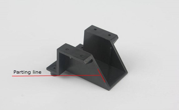
The parting line is where the two halves of the mold meet to produce the final product. If there is any mismatch or misalignment in the parting line design, it can result in flash defects on the molded part. Therefore, it is important to design a parting line that is simple and straight to minimize these defects. A simple parting line is easier to manufacture, requires less maintenance, and can provide a better overall finish for the final product.
When designing the parting line, it is generally preferable to place it on sharp edges rather than filleted surfaces. This helps to minimize the need for a mold with tight tolerances, which can increase production costs. It is also important to consider the visual impact of the parting line on the final product. The line should be designed in a way that minimizes its visibility and does not cross critical surfaces or features such as text or logos. This can help to ensure that the final product meets the required aesthetic standards and enhances the overall quality of the injection molding process.
Draft Angle
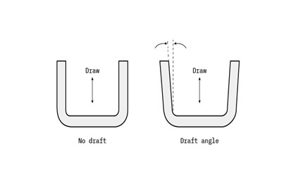
Draft angles on surfaces of injection-molded parts allow for easy removal from the mold without damage. The required draft angle depends on factors like wall thickness, material shrinkage, post-production finishing needs, etc.
The average draft should increase by 1 degree per inch of depth, but a minimum of 1.5 to 2 degrees is typically safe for most components. Heavy textures may require up to 5 degrees per inch of depth. An inadequate draft can cause aesthetic flaws like drag marks. You can add draft angles when designing for injection molded parts using CAD systems. However, it would be best to do this in the final stages of design to minimize complexity.
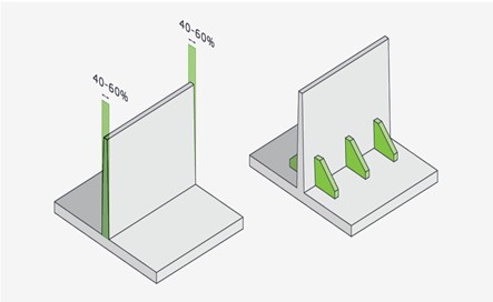
Ribs and Bosses
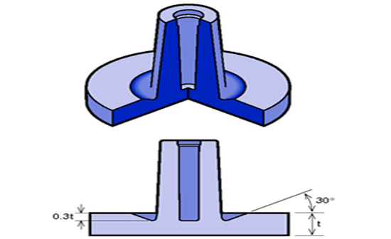
Ribs help to strengthen part walls where two walls meet at a 90-degree angle. They help increase the structural integrity and increase the load-bearing capacity of the part. On the other hand, bosses have raised areas used for fastening and aligning parts. They also strengthen parts in areas like screw holes and slots.
The base thickness of support ribs should be a maximum of two-thirds the thickness of the adjoining wall. Rib height should not exceed 2.5 times the nominal wall thickness (2.5T). It is important to consider shrinkage. To avoid sink marks, the thickness of the boss should not exceed 60% of the overall wall thickness.
Gate Location and Type
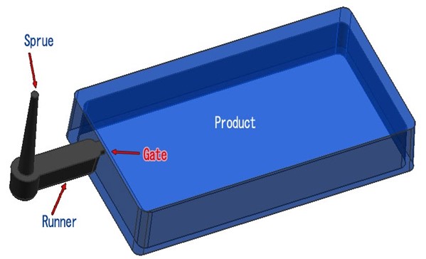
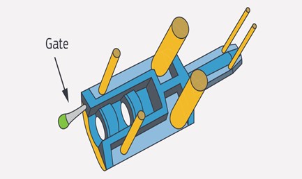
The gate in injection molding is an essential component that directly connects to the plastic part and controls the flow of melted plastic resin into the cavity. The size, shape, and location of the gate have a significant impact on the finished product. It affects its structural integrity and exterior appearance.
There are four common types of gate designs for different types of injection molds: edge, sub, hot tip, and sprue. As the name suggests, edge gates are located at the edge of flat parts and leave a scar on the parting line. Sub-gates are common and have different variations, such as banana, smiley, and tunnel gates. They require ejector pins to trim automatically and are helpful when moving the gate location away from the parting line for better filling.
Hot tip gates are only used with hot runner injection molds. They are often located at the top of the mold for round or conical geometries. On the other hand, sprue gates are ideal for single-cavity molds that are large and cylindrical. They often leave a large scar at the point of contact but are easy to manufacture and maintain.
The gate design and type depend on the part design, material choice, dimensional requirements, and aesthetic needs of the end product. A key design consideration is to locate gates away from high-stress or impact areas to minimize the risk of defects. It is also essential to eliminate secondary de-gating operations and place them in the thickest area to achieve the best fill. In some cases, multiple gates may be necessary depending on the part’s size, geometry, and plastic polymer type.
Ejector Pins
This is a crucial part of the injection molding setup that helps push parts out of the mold after they are sufficiently cool. They often leave marks on the parts. Therefore, you need to design them to be on flat surfaces perpendicular to the movement direction of the pin.
Part shape, draft angles, wall depth, and wall texture determine the number and placement of pins. These factors will influence how the part adheres to mold walls. Material choice will also affect the size and placement of these pins. For instance, stickier resins will require more ejection force. Likewise, softer plastic polymers will require wider or more pins to help distribute the ejection force to avoid molding defects.
Undercuts and Threads
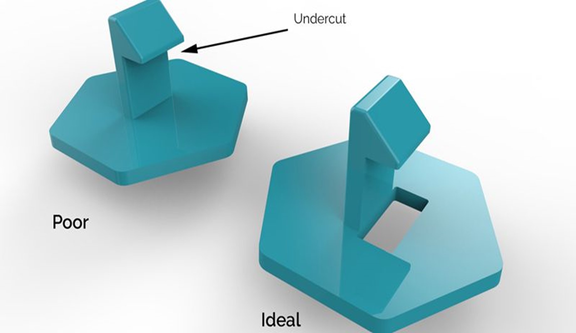
Undercuts and threads are recessed or overhanging features that make it difficult to eject a plastic part from the mold with a single pull. The design should ensure that the part can be ejected with a single, unidirectional pull. Doing this will help keep the injection molding cost low. Therefore, it is important to avoid threads and undercuts while designing parts for injection molding.
To avoid undercuts, you can orient features parallel to the draw line, and incorporate lifters and sliders into the design. Lifters help release internal undercuts without draft. Once the part cools, the lifter can push up at an angle to remove the undercut from the mold. In contrast, sliders use angled pins attached to the core mold to release external undercuts.
Round Corners
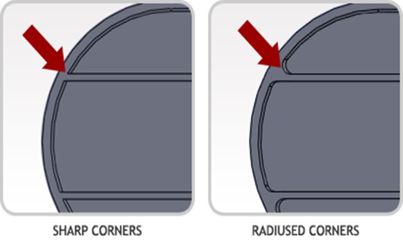
To improve the efficiency and quality of the injection molding process, designers and engineers should aim for rounded features rather than sharp corners and edges. Sharp edges require more pressure to fill, increasing the risk of part damage and defects during ejection. Rounded internal and external corners help plastic flow more smoothly and reduce residual stress and cracking.
The radius of internal corners should be at least 50% of the adjacent wall thickness. On the other hand, external corners should be 150% of the adjacent wall thickness. For vertical features like bosses and snap fits, the base should be rounded. The boss radius should be 25% of the adjacent wall and a minimum radius of 0.381mm (0.015 inches).
Surface Finishing
Plastic parts can have different surface finishes that affect their texture, look, and feel. Choosing the right finish is crucial to the design phase as it determines the tooling and material needed. Rough finishes require higher draft angles and impact the material selection. The mold surface may also need preparation to achieve the desired finish. The slightest imperfection in the mold surface can transfer to the molded part. The more post-production finishing needed, the higher the cost and longer it takes to complete the mold.
Material Selection
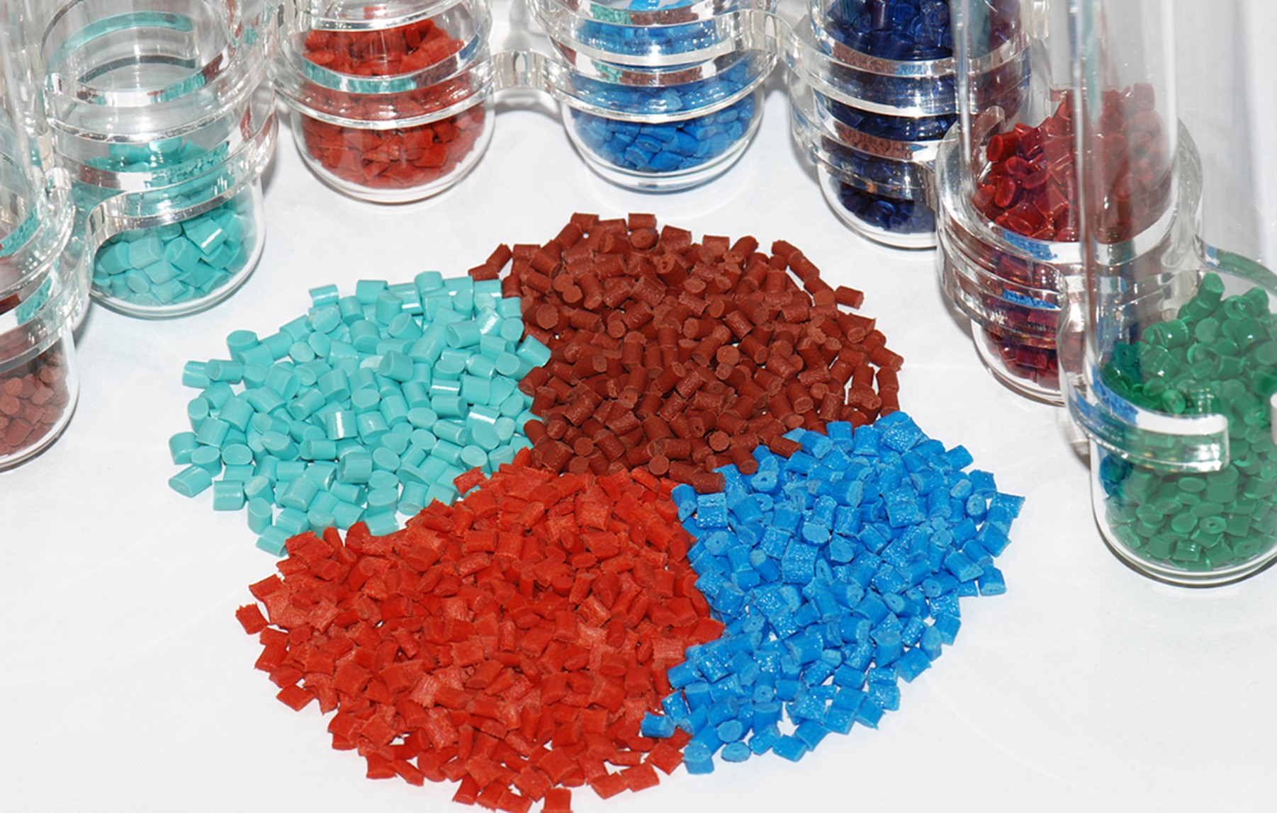
Injection molding involves using a variety of plastic resins, each with its specific physical and mechanical properties. Material selection impacts the part’s functionality in its intended environment. Key considerations when selecting injection molding materials include material shrinkage rate, assembly, and cost.
Material shrinkage rate varies based on the plastic type and processing conditions, which can affect part performance and geometry. You should also consider the material’s ability to handle assembly processes such as mechanical fastening and welding. While the desirable attributes of the plastic material are essential, you must also consider the cost of purchasing, machining, and finishing the plastic to minimize production costs.
Injection Mold Design Guide
Injection mold design and production are essential processes in plastic parts manufacturing. The mold tooling helps define the shape of the intended plastic part. Therefore, all mold components must be in the proper condition for smooth injection molding.
Here are some tips to consider when designing the injection mold tooling.
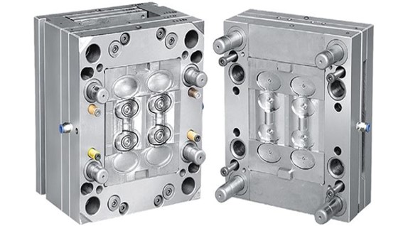
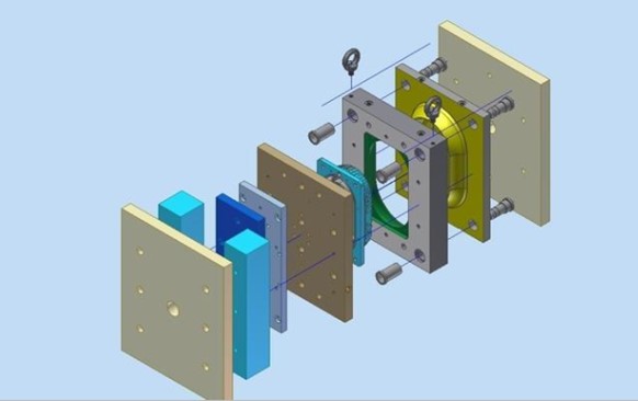
Mold Base and Cavity Layout
The mold tooling includes the mold base, cavity, core inserts, and other components. The mold base provides the foundation for the mold, while the cavity and core inserts create the shape of the part. The design of the mold tooling affects the accuracy and consistency of the molding process.
The mold must be durable, easy to maintain, and easy to disassemble and assemble for repairs and maintenance. The mold tooling should be built with precision to ensure proper alignment of the cavity and core. The cavity layout of the mold base must also give access to the hollow and core inserts, permitting simple maintenance and repair. This reduces the risk of defects and improves part quality.
Cooling System Design
The cooling system is an essential aspect of injection mold design. It controls the temperature of the mold cavity and the plastic material. Cooling is critical because it helps solidify the plastic and control shrinkage.
The design of the cooling system should ensure uniform cooling throughout the mold cavity. Cooling channels should be designed close to areas that take longer to cool so that they will not interfere with the gating and runner systems. Machinists should also optimize the design to achieve the shortest possible cycle time.
Runner and Gate Design
The runner and gate system controls the flow of molten plastic into the mold cavity. The gate is the entry point for the plastic to enter the cavity, and the runner system channels the plastic to the gate. The gate and runner system design affects the efficiency of the molding process and the quality of finished products.
The gate size, location, and shape should optimize material flow, minimize part stress, and avoid defects in the part. The runner system should minimize pressure drop, ensure the even distribution of material, and avoid dead spots where plastic can accumulate and cause defects.
Ejection System Design
The ejection system removes the finished part from the mold cavity. The ejection system design should consider the part geometry, the number of undercuts, and the part’s stiffness. To ensure that the part is not damaged during ejection, designers can use ejector pins, sleeves, or hydraulic ejection systems. Additionally, the ejection system must be designed to withstand the necessary forces required to remove the part from the mold. It is also important to consider the ejection system’s placement about the gating and runner systems, to avoid interference.
Mold Materials and Surface Finishing
The material used for the mold affects its lifespan and the quality of the finished product. To ensure optimal performance, the mold material should have a high melting temperature, good thermal conductivity, and excellent wear resistance. Choosing a suitable material can help reduce cycle time, extend the mold’s lifespan, and reduce the risk of part defects.
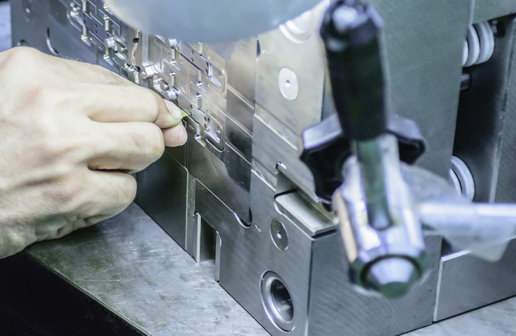
Each mold is unique and requires careful consideration during the machining process. The materials used must be machined with precision to avoid surface defects that can transfer to the molded part. It is important to remove visible marks on the mold surface left by end mills through additional finishing, like bead blasting or polishing. The degree of finishing required can impact the cost and timeline of the mold tooling process.
RapidDirect offers outstanding injection mold tooling services to improve the molding process and the quality of molded parts. We provide comprehensive DFM analysis for your injection molding projects to improve mold and part design. As a result, you can save enough time and money, while getting superior-quality products.
Injection Molding Process Control for Quality Plastic Parts
The injection molding process is a highly precise and efficient method of manufacturing plastic components. However, to ensure high-quality plastic products, it is essential to have a strict process control throughout the manufacturing process. Before we go into the key steps for achieving process control in injection molding, let’s have a brief overview of the injection molding process.
Injection Molding Process Overview
Injection molding involves melting plastic polymers and solidifying them under pressure in molds that give the components their shapes. This continuous cycle includes many steps. After heating the plastic resins, the gate opens upon applying the appropriate pressure to the mold tooling. The melted plastic is then injected into the mold.
Once the molten resin reaches the end of the barrel, the gate is closed. The two parts of the mold then close simultaneously and are held together by the clamp pressure. After the holding phase, the screw retracts, and the part cools in the mold. Once the part cools, the mold opens, and ejector pins or plates push the part out. The finished part is then ready for finishing processes.
With this in mind, let’s check out the various aspects of the injection molding process control:
Machine Selection and Setup
Selecting the right injection molding machine and setting it up correctly will help achieve process control and produce high-quality plastic parts consistently.
Consider the following factors:
- Clamping Force: the machine should provide sufficient clamping force to hold the mold securely during the injection molding process.
- Injection Unit Size: injection unit should be large enough to provide sufficient melt volume to fill the mold cavity without overpacking or under-filling the part.
- Screw Type and Size: the screw should provide consistent melt quality and flow rate. The screw diameter should also provide the right shot size and melt density.
- Temperature Control: the machine should have a high-quality temperature control system to maintain uniform heating and cooling throughout molding.
- Material Handling: the machine should also have an efficient material handling system that can transport the material from the storage area without contamination.
Overall, there should be room for tracking critical process parameters such as temperature, pressure, and cycle time. Machinists should be able to easily detect any variations in the process parameters and adjust them in real time to prevent defects in the finished product.
Process Parameters and Optimization
Injection molding process control involves monitoring and adjusting several parameters for optimal results. Here are some critical parameters to consider:
- Injection Pressure and Speed: These parameters determine how quickly the molten plastic material fills the mold cavity. The injection pressure should be high enough to fill the mold cavity completely. However, it should not be so high that it causes flash or part distortion. It should ensure that the material fills the cavity in the shortest possible time without degrading.
- Injection Temperature: Injection temperature affects the flow and viscosity of the plastic material. The plastic material should be heated to its melting point and kept at a stable temperature throughout the injection molding process. Machinists can monitor and control the temperature with thermocouples at different points in the mold cavity.
- Holding Pressure and Time: The holding pressure should be such that it prevents the material from flowing back into the injection unit. The holding time should allow the plastic material to cool and solidify completely. The time will depend on the part’s wall thickness and complexity.
- Cooling Time: The choice of cooling time should depend on the material’s thermal properties and the part’s wall thickness. Thermocouples can also help monitor the cooling time. Machinists can adjust the time by changing the cooling channel layout or increasing the size.
- Ejection: The ejection system should ensure smooth and consistent ejection, avoiding damage to the part and the mold. Ejection force should also depend on the part’s size and complexity.
Quality Control and Inspection
Quality control and inspection aim to guarantee that the molded parts meet the quality and performance requirements. There are different aspects, including process capability studies, visual and dimensional inspection, and functional testing. They help identify sources of variability and suggest improvements to the process.
Efficient quality control ensures that molded parts are free of defects and surface blemishes and that they meet the specified tolerances and functional requirements. Quality control and inspection processes must be done regularly to ensure that the parts meet the specified quality, safety, and performance standards.
Common Injection Molding Design Issues and Solutions
Various injection molding defects can occur during manufacturing, impacting the product’s functionality. These defects can occur due to molding parameters, material choice, etc. However, you can easily prevent design defects by adjusting the molding process. However, some issues may require you to redesign the mold tooling or replace production equipment.
Let’s explore some of the typical injection molding design issues and how you can resolve them.
Sink Marks and Warping
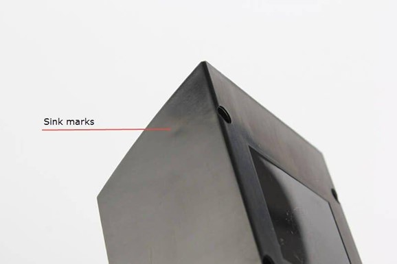
A sink mark is an injection molding defect that occurs as tiny depressions on flat surfaces of molded parts. Sink marks typically happen due to the shrinking of a molded part’s inner component, causing the material to sink inward from the outside.
Warpings are unexpected bends and twists on injection molded components due to the irregular internal shrinkage in the cooling process. It puts unintended stress on various areas of the molded component. This stress forces the molded parts to bend and twist while cooling. You can notice this in parts that are flat but have gaps when placed on a flat surface.
Causes
- Extremely high melt or mold temperature
- Incredibly low holding or injection pressure
- Defective mold structure design
- Insufficient holding or cooling time and pressure
Solutions
- Ensure a gradual and longer cooling process to prevent internal stresses
- Maintain even wall thickness in mold design to facilitate the flow of molten plastic in a single direction through the mold cavity
- Use adequate holding pressure and time to allow the cooling of material near the part’s surface
- Reduce the mold or material temperature
Flash and Part Sticking
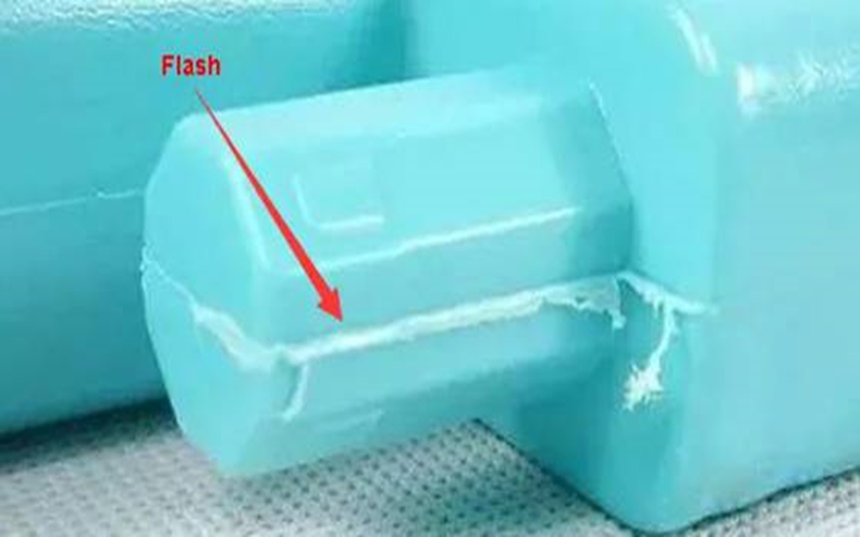
Flash, spew, or burrs refer to a situation where excess molding material appears as a thin line at the edge of the component. It usually occurs due to the flow of some material out of the intended channels. Although a flash counts as a subtle defect, it may become a severe product defect if it affects its functionality.
On the other hand, part sticking involves the molded part adhering to the mold surface, making it difficult or impossible to eject.
Causes
- Inappropriate exhaust system design and control
- Inadequate clamping force
- Deficient mold design and degraded molding condition
- Excessive injection pressure or high mold temperature
- Inadequate mold release agents
- Insufficient cooling time
Solution
- Ensure the exhaust channel has the right size
- Apply high clamping force for the plate to avoid space in between
- Redesign the mold to allow smooth flow of molten material and proper ventilation
- Coat the mold properly with the right release agents
- Optimize the injection pressure, mold temperature, and cooling time for the specific material used
Short Shots and Burn Marks
A short shot is a defect on molded parts when the molten material fails to fill the entire mold cavity. As a result, the molded component is incomplete after cooling and ejection. Short shots are considered severe defects because they affect the molded part’s appearance and function.
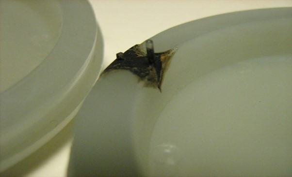
Burn marks as black rust-colored marks on the surface or edges of the molded component. Although these defects do not usually impact the integrity of parts, they become a severe problem when it burns the molded component such that it causes degradation.
Causes
- Insufficient injection pressure
- Trapped air pockets obstruct the free flow of molten plastic
- Using material with extremely high viscosity
- Inappropriate design of the gate and runner system
- Extremely high melting temperature
Solutions
- Widen the available vent or add more air vents to ensure better ventilation
- Use sufficient mold temperature to avoid rapid and inconsistent material cooling
- Reduce the injection speed to mitigate the risk of trapped air
- Increase injection molding speed and pressure or use a thinner base material for better flow
Gas Traps and Voids
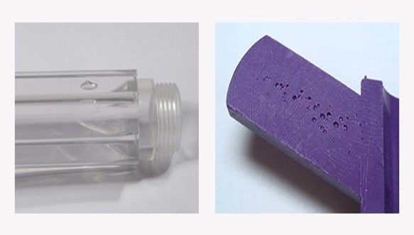
These air trap defects are among the most critical flaws in injection molding. They appear as trapped air or air bubbles in the molded components. These trapped bubbles can cause structural and aesthetic faults. Likewise, if the air originally within the mold gets hot and compressed tight enough, it can explode, destroying both the molded component and the mold.
Vacuum voids are trapped air bubbles found in injection molded parts. Manufacturers sometimes refer to these defects as air pockets. Although quality control experts categorize voids as minor defects, more substantial voids can weaken the molded component.
Causes
- Poor ventilation in the mold
- Uneven filling of the mold cavity
- Trapped air compression and ignition
- Insufficient molding pressure
- Material’s vulnerability to voids due to significant changes in its density
Solutions
- Increase the mold temperature
- Redesign or retool the runner system and gate positioning
- Use materials with lower viscosity to prevent air bubbles from forming
- Limit the cycle time to prevent trapped air from compressing and igniting
- Increase the injection pressure to expel trapped air from the cavity effectively
Parting Line Mismatch and Deflection
Parting line mismatch is a defect where the two halves of the mold do not line up correctly. It results in a visible seam or gap along the parting line of the molded part. Deflection occurs when the molded part warps or bends out of its intended shape during cooling. Both defects can result in parts not meeting the required specifications, leading to increased scrap rates and reduced productivity.
Causes
- Uneven clamping force
- Dimensional variations in mold components
- Too high injection pressure and temperature
- Thermal expansion of the mold
- Insufficient cooling time
Solutions
- Ensure proper clamping and alignment of the mold
- Keep mold temperature consistent throughout the molding process
- Optimize injection molding parameters for the material used
- Post-molding heat treatment can reduce residual stress
Get Plastic Parts with High Quality and Visual Appealing
Getting superior-quality injection molded parts require partnering with the most reliable manufacturing company. RapidDirect is a leading provider of high-quality plastic parts through advanced injection molding services. With an excellent combination of skilled technicians and state-of-the-art equipment, we offer parts with exceptional precision and visual appeal.
RapidDirect offers a range of materials and finishing services to improve the quality of injection molds and plastic parts. Our experienced technicians can provide suggestions to optimize your mold design and recommend suitable materials and finishing for your plastic part. We understand that an injection molding project can be complicated. Therefore, we offer a streamlined quotation process and provide a DFM analysis report to help you confirm your design concept before starting manufacturing.
Our experienced engineering team is also available to offer support throughout the entire manufacturing process. Submit your design file today to get instant quotes and begin your injection molding journey.
Conclusion
Injection molding is a versatile and efficient technique for creating high-quality custom plastic components for various industries. However, the process is incomplete without following a set injection molding design guide. This will give you a detailed understanding of what you need and how to complete the process.
The injection molding design rules discussed in this article will help you optimize the process, ensuring cost-effective production and shorter cycle times. Design errors are costly. Contact RapidDirect today for insight into your injection molding design. We are always ready to help you achieve better results.