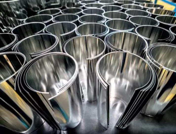
Sheet metal fabrication is a crucial process in the manufacturing industry, with numerous applications in construction, automotive, aerospace, and other fields. The versatility of sheet metal and its ability to be formed into various shapes and sizes make it a popular choice for creating complex and intricate designs.
However, to ensure the success of any sheet metal fabrication project, it is essential to have a solid understanding of the design principles and best practices. In this article, we will provide a comprehensive guide to sheet metal fabrication design, including tips for material selection, geometric constraints, and cost-effective design strategies.
Whether you’re a seasoned engineer or a novice designer, this guide will help you create high-quality sheet metal parts that meet your project’s requirements and specifications.
Overview of Sheet Metal Fabrication
For manufacturing purposes, sheet metal is classified as anything thinner than 0.25 inches. All sheet metal parts come with the requirement of having consistent width, which limits some of its applications. But ensures that the resulting part is able to fulfill the requirements of durability and longevity.
Generally, sheet metal parts are common in applications like automobile chassis and other areas where the strength-to-weight ratio is important. Sheet metal has a lower thickness and parts made of it are generally hollow. This means that they’ll weigh less but will have the same capacity to sustain greater loads.
There is no point in opting for precision processes for simple applications. However, avoiding precision sheet metal fabrication for high-value applications is also not feasible. Because it may cause damage to sensitive equipment due to wear and tear.
The Working Principle
The working principle behind sheet metal fabrication is quite simple. It depends on the elasticity of the metal and the fact that cold-rolled metal performs better in terms of durability. Sheet metal fabrication consists of two methods, cutting and forming.
As its name suggests, cutting requires removing a part of the sheet to obtain the desired shape. On the other hand, forming is a bit difficult method consisting of three different processes. They mostly work together to create the form of the object you need. The process requires careful consideration of the design and manufacturability to minimize any waste and ensure perfection.
In most cases, manufacturers rely on CAD files in either the DXF or DWG model to ensure compliance with the available design. In most projects, the cutting and forming processes work in tandem as it allows for quicker results. Moreover, sheet metal fabrication generally requires no post-processing but may need some finishing and joining depending on the application.
The 4 Main Sheet Metal Fabrication Techniques
The sheet metal fabrication process consists of two main processes; forming and cutting. These two techniques work together to create the final form of any product. While cutting is a simple process, forming has further classifications, namely stamping, bending, and punching.
Here are the basic details related to the main techniques for creating sheet metal parts:
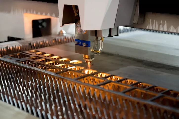
1 – Cutting
The cutting process removes the excess sheet metal in a particular shape to obtain the final form. There are 3 main approaches when it comes to cutting sheet metal:
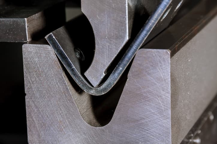
2 – Bending
The bending process simply applies a great force on the sheet metal at a specific point to obtain the required shape. In some cases, the area under the bend might need some preparation. For instance, bend notches not only show the technician the location of the bend but can also facilitate the process itself.
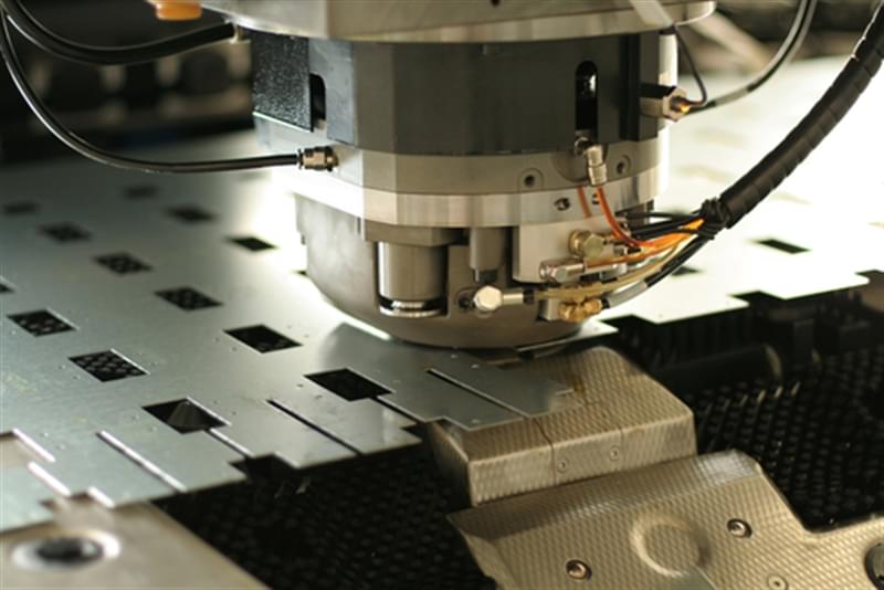
3 – Stamping
To create a complex part in a limited time, manufacturers often select the stamping process, which is a complex form of form. The process uses a combination of different techniques using shearing, bending, and stretching to create new shapes out of sheet metal.
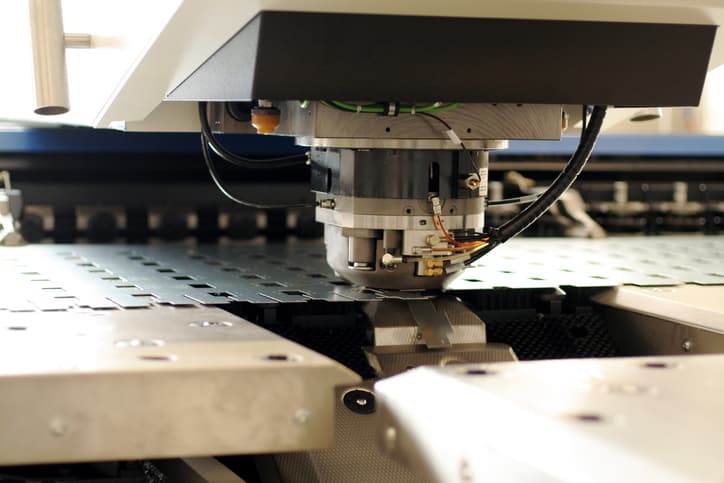
4 – Punching
To create a complex part in a limited time, manufacturers often select the stamping process, which is a complex form of form. The process uses a combination of different techniques using shearing, bending, and stretching to create new shapes out of sheet metal. Furthermore, some stamping processes even go as far as joining multiple pieces using different techniques as well.
The Main Advantages and Limitations of Using Sheet Metal for Fabrication
Sheet metal parts designs are quite popular in many industries because of their perceived advantages. However, there are multiple limitations to the process as well. These advantages and limitations are among the most important design considerations for manufacturers as they determine the correct applications of the metal.
| Advantages | Disadvantages |
| Quick turnaround when compared to other manufacturing methods. | Difficult to make complex designs with intricate details, which can limit the range of shapes and forms that can be produced. |
| High-quality parts for both production and prototyping. | Requires significant investment for tooling and other equipment, which can be a barrier to small-scale production. |
| Versatile enough to work with several metals, such as steel, aluminum, and copper. | Have longer lead times compared to other fabrication methods due to the multiple stages involved in the process, such as cutting, forming, and finishing. |
| Delivers a high strength-to-weight ratio because of the hollow design. | Requires skilled labor, which can be expensive |
| Needs no post-processing in most cases. |
Guidelines for Sheet Metal Fabrication Design
As stated before, the design for sheet metal fabrication needs attention to some design requirements. Most of those requirements depend on the overall design of the product. For instance, a simple product would not have many requirements but an intricate geometry would naturally need more processes to be market-ready.
Generally, sheet metal fabrication requires a series of best practices that can ensure perfection and deliver the best quality in the shortest time. The general guidelines for sheet metals include the following 5 categories.
1 – Tolerances
Tolerance is one of the most important parameters for a variety of applications. The general rule of thumb states that more precision requires more resources and has additional costs. So, the tolerances should be according to the application.
The perfect example of this can be the automobile industry.
The precision required for the door or any other part of the body would obviously be lower than the requirement for the chassis or some other integral part. Generally, tolerance requirements depend on the project requirements but that approach can have a lot of inconsistencies in the product.
Many manufacturers and industries prefer set quality standards to avoid those inconsistencies. While these standards are not a one-size-fits-all solution, they are an excellent tool for maintaining consistency and performance. Furthermore, compliance with industry standards also makes it easier to fulfill industrial requirements and build consumers’ trust in the brand.
For sheet metal fabrication, the prevalent standard is ISO 2768. This covers the tolerance requirements for multiple industries while maintaining the perfect balance between costs and processing capabilities.
General Tolerances
For sheet metal fabrication, there are a few general tolerances that the industry uses everywhere. They are in compliance with international standards. However, there will be several exceptions to them in the case of sensitive applications like aerospace and automobile where precision is critical for performance.
| General Tolerances of Sheet Metal Fabrication | ||
| Feature | Prevalent Tolerance Range | Additional Notes |
| Wall thickness | 0.9mm to 20mm | |
| Offsets | 0.3mm to 0.7mm | |
| Curls | >2x material thickness | Anything less than the recommended curl dimension would make the sheet brittle. |
| Bends | 0.9mm – 1.2mm1.8mm – 2.4mm3.8mm – 5.0mm7.5mm – 10mm15mm – 20mm | A +/- degree deviation is expected on all bends. Moreover, any other specifications will add to your costs. |
| Hems | Inside dia = material thickness with return length to be 4x the thickness | |
| Countersinks | Major dia = +/- 0,254 mmMinor dia > 2/3 thickness | |
| Holes and slots | Dia > material thickness | A diameter less than the material thickness would cause cracks in the sheet. |
| Notches and tabs | Notch width > 1.5x thickness Length > 5x thickness |
Forming Basics
In this process, a flat sheet of metal is bent into a predetermined form by applying pressure. The process requirements and details change according to the type of bending process. While there are numerous ways, the following three methods of sheet metal bending are the most common.
- Brake pressing: Manual process uses a clamping bar and a plate to form the metal sheet. The process is only suitable for prototyping and small-scale productions.
- Roll bending: The same fundamentals, but the result would be in the form of cylinders, cones, or other arcs.
- Press brake bending: The most advanced bending process that uses hydraulic machines with a punch and dies. This is suitable for metal sheets up to the thickness of 6mm and can easily produce precise features.
Integral Parameters for Sheet Metal Bending
When it comes to the bending process, there are multiple parameters that manufacturers and designers must consider. These design requirements are what fundamentally characterize any sheet metal bend and it’s advisable to adhere to their standards to ensure excellent results.
Here are the 6 most important parameters for any sheet metal bending operation.
- Bend Line: The bend line is a straight line on the sheet’s surface that marks the beginning to the end on both sides of the bend. The industry standard for bend lines is to keep the distance of 5x the sheet thickness between the inside edge and outside of the bend.
- Bend Radius: The bend radius refers to the distance from the bend axis to the inner surface of a material between two bend lines. It is generally advisable to use a bend radius that is at least as large as the thickness of the material. A larger bend radius is even better, but using a smaller radius than the material thickness can reduce the load-bearing capacity of the part.
- Bend Angle: The angle created by the bend with the imaginary perpendicular line coming from the axis. Rather than a specific number, the industry practice for bend angles is to ensure that the flange length must be 4 times the thickness. It’s also good practice to keep all bend angles the same.
- Neutral Axis: The neutral axis is the portion of a sheet that remains at its original length because it is neither stretched nor compressed. It is an independent parameter, and there is no legal limit or guideline for its location. However, the accuracy of other factors such as bend radius and angle play a crucial role in determining the performance of the final product. Therefore, the more precise these factors are, the better the product is likely to perform.
- The K-Factor: The K-factor of a material is a measure of its location, determined by dividing the distance between the material and its thickness (t) by its T. The K-factor is subject to a range of factors, including the material type, bending process, bend angle, and others. To ensure optimal results, the K-factor should fall within the range of 0.25 to 0.50. The K metric can be calculated by the formula K = T/t.
- Bend Allowance: To make accurate and consistent bent parts, it’s important to carefully measure and account for the arc length and the distance between the neutral axis and the bend lines. You should also use accurate bend allowances that are appropriate for the material and thickness to bend, as well as the type of bending process being used (e.g., air bending, bottom bending, or coining).
Cutting Basics
Another important process in sheet metal fabrication is cutting. In many cases, it’s an easier alternative that delivers fast results with acceptable precision. During the design phase, sheet metal design guidelines focus on the following 5 parameters.
Material Selection
During the process, the material characteristics play an important role in determining the suitable process for the specific material. Consider the example of Aluminum and Steel to understand this better. Naturally, cutting Aluminum would be simpler than dealing with steel because of steel’s relative strength and durability.
For material selection, the best practice is to consider manufacturability as well. For instance, if both steel and aluminum can sustain loads of a particular operation, it’s not always smarter to go for the stronger alternative (steel) without considering the manufacturing capabilities.
Hole Diameter
When designing a product that involves drilling holes in a sheet, it is important to consider the thickness of the sheet and the diameter of the hole. A general rule of thumb is to ensure the diameter of the hole is at least equal to the overall thickness of the sheet.
If the diameter of the hole is too small in comparison to the thickness of the sheet, it can result in the formation of cracks and brittle areas around the hole. These cracks can propagate over time and lead to durability issues that can negatively impact the overall performance of the product.
Therefore, it is important to make sure the diameter of the hole is appropriate for the thickness of the sheet in order to maintain the structural integrity and long-term durability of the product.
Localized Hardening
When materials are cut, the process can generate significant amounts of heat, which can have an impact on their properties. Specifically, the region surrounding the cut may become overheated, leading to localized hardening. To prevent this problem, it is recommended to slow down the cutting speed overall and to use coolants to regulate the temperature in the affected area. By doing so, the risk of localized hardening can be minimized.
Distortion
Distortion in sheet metal fabrication refers to the warping, bending, twisting, or buckling of the metal sheet during the manufacturing process. This issue can occur due to a variety of factors, such as changes in temperature, stress, or pressure during the fabrication process. Distortion can cause significant problems in the final product, such as dimensional inaccuracies, poor fitment, and reduced strength.
Kerf
The kerf is directly related to the width of the cutting tool used and the thickness of the material being cut. Essentially, it represents the width of the material that is removed by the cutting tool, and it determines how much material is wasted in the cutting process.
For example, if a laser beam has a kerf of 0.1mm, and a cut is made through a sheet of metal that is 1mm thick, then the total width of material removed from the sheet will be 0.2mm (0.1mm from each side of the cut). The kerf width may vary depending on the type of cutting process, the type of material being cut, and the thickness of the material.
It’s important to consider the kerf when designing parts for sheet metal fabrication, as it can affect the final dimensions of the part. If precise dimensions are required, then the designer should take the kerf into account and adjust the design accordingly. Additionally, the kerf can also impact the cost of the fabrication process, as more material may be wasted with a wider kerf.
Common Features in Sheet Metal Parts
The sheet metal design deals with multiple features that allow these parts to fulfill the requirements of the industry. Here are the 6 main common features that sheet metal parts will often have.
| Parameters | Description | Recommendations |
| Corner Fillets | Corner fillets are rounded edges or corners on sheet metal parts that are created to avoid sharp edges, which can be dangerous and can also cause stress concentration in the metal, leading to failure. | – Size: The size of the fillet should be at least equal to the thickness of the sheet metal. In other words, a 2mm fillet should be used for sheet metal that is 2mm thick or less. – Symmetry: The fillets on a part should be symmetrical. This means that the fillets on opposing corners should be the same size. – Uniformity: The fillets should be uniform in size throughout the part. This means that the fillets on all corners should be the same size. – Placement: Fillets should be placed in areas where stress concentrations are likely to occur. This includes areas where the sheet metal is bent or where there is a change in shape or direction. – Radius: The radius of the fillet should be as large as possible. This helps to distribute stress more evenly and reduces the likelihood of stress concentrations. – Design: The design of the part should be such that fillets can be easily added without compromising the integrity of the part. |
| Ribs | Raised features that are typically perpendicular to the surface of the sheet metal part. They are used to add strength and stiffness to the part without adding much weight. | – Keep the rib thickness to no more than 60% of the sheet metal thickness to avoid creating stress concentrations. – Use fillets to smooth the transition between the rib and the surrounding material, which will help to distribute stresses more evenly. – Avoid placing ribs too close together or too close to bends, as this can create weak spots in the material. – Consider using tapered or variable-height ribs to distribute stresses more evenly. |
| Embossment | Recessed features that are typically parallel to the surface of the sheet metal part. They are used to add depth or texture to the part, or to create a space for another component to fit into. | – Keep the depth of the embossment to no more than 50% of the sheet metal thickness to avoid creating stress concentrations. – Use fillets to smooth the transition between the embossment and the surrounding material, which will help to distribute stresses more evenly. – Avoid placing embossments too close together or too close to bends, as this can create weak spots in the material. – Consider the impact of the embossment on the overall appearance of the part, and make sure it is aligned with any branding or design requirements. |
| Round Boss | A raised circular feature in sheet metal fabrication that is used to add strength and rigidity to a part. It is typically created by punching or forming a circular depression in the sheet metal, which causes the metal around the perimeter of the depression to bulge out and form a raised circular feature. | – Choose the right size and location: carefully consider the placement and size of the boss to ensure that it will provide the necessary support and strength without interfering with other components or creating manufacturing challenges. – Use the right tooling: Creating a round boss requires specialized tooling, such as a punch and die set or a forming tool. It’s important to use the right tooling for the job to ensure that the boss is formed correctly and that the sheet metal is not damaged in the process. – Consider material thickness: The thickness of the sheet metal will affect the size and shape of the round boss that can be formed. Thicker materials may require larger or deeper bosses to provide the necessary strength and rigidity. |
| Dimple Feature | Dimples are often used for a variety of reasons, including: To improve the stiffness and strength of a sheet metal part by adding reinforcement. To create a smooth and flush surface for fasteners or other components to be attached. To provide clearance for other parts or components. | – Consider the size and location of the dimple carefully. Dimples should be placed in areas where they will provide the most benefit, and their size should be appropriate for the application. – Overly large or deep dimples can weaken the material, while too small or shallow dimples may not provide sufficient reinforcement. – Choose the right tool for the job. There are a variety of tools that can be used to create dimples, including punches, dies, and form tools. The tool you choose will depend on the size and shape of the dimple, as well as the type of material being used. – Take into account the thickness and material of the sheet metal. Different types of sheet metal may require different techniques or tools for creating dimples, and thicker materials may require more force or a larger tool. – Be aware of any limitations or restrictions in the design. Dimples can be useful features, but they may not be appropriate for every application. Make sure that the design takes into account any potential issues or challenges that may arise from adding dimples. |
| Louver Feature | The primary purpose of louvers is to improve the airflow and ventilation in the enclosure or panel that they are installed on. Louvers can be designed to fit a specific purpose, such as directing air in a particular direction, reducing noise, or providing protection against dust, dirt, or moisture. | – Size: The size of the louvers should be carefully chosen based on the required airflow and the amount of space available for installation. Louvers that are too small may not provide enough ventilation, while those that are too large may compromise the structural integrity of the panel. – Orientation: The orientation of the louvers should be chosen based on the direction of airflow and the location of any potential obstructions or obstacles that could affect the flow of air. – Shape: The shape of the louvers can have an impact on the efficiency of the ventilation system. Louvers that are designed with a streamlined, aerodynamic shape can improve airflow and reduce turbulence. – Material: The material used for the louvers should be selected based on the intended application, as well as the environmental conditions the panel will be exposed to. For example, stainless steel or aluminum may be better suited for outdoor applications where exposure to the elements is a concern. – Manufacturing method: The manufacturing method used to create the louvers should be selected based on the desired precision, consistency, and cost-effectiveness of the fabrication process. |
| Round Knockout | Round knockouts can be used to create holes of various sizes, depending on the size of the punch and die used. They are commonly used in sheet metal fabrication for applications such as electrical boxes, HVAC systems, and enclosures. | – Choose the right size: Make sure to use the correct size punch and die for the size of hole you need. Using the wrong size can result in a hole that is either too small or too large. – Use the right material: Round knockouts are typically designed to work with specific types of sheet metal, so make sure to use the appropriate knockout tool for the material you are working with. – Keep the punch and die sharp: Over time, the punch and die can become dull and start to deform, which can result in poor-quality holes. Keep them sharp and in good condition for best results. – Consider the thickness of the material: Round knockouts are best suited for thinner materials. If you need to create holes in thicker sheet metal, you may need to use a different tool or technique. – Be mindful of burrs: When using round knockouts, there is a risk of creating burrs around the edge of the hole. Make sure to remove any burrs with a deburring tool or sandpaper for a clean finish. |
Material Thickness
The recommended thickness for sheet metal depends on the specific application and the material being used. Generally, thicker metals provide greater strength and durability, while thinner metals are more flexible and lightweight. Common thicknesses for sheet metal range from 0.5 mm to 6 mm, but can vary based on the material and intended use. Here is a chart showing the recommended material thickness for some common metals used in sheet metal fabrication.
| Metal | Gauge | Millimeters | Inches |
| Steel/Stainless Steel/Aluminum | 22 | 0.8 | 0.031 |
| Steel/Stainless Steel/Aluminum | 20 | 1.0 | 0.039 |
| Steel/Stainless Steel/Aluminum | 18 | 1.2 | 0.047 |
| Steel/Stainless Steel/Aluminum | 16 | 1.6 | 0.063 |
| Steel/Stainless Steel/Aluminum | 14 | 2.0 | 0.079 |
| Steel/Stainless Steel/Aluminum | 12 | 2.5 | 0.098 |
| Steel/Stainless Steel/Aluminum | 10 | 3.2 | 0.126 |
Note: This chart provides general guidelines and the appropriate material thickness for a given application may depend on additional factors.
Common Sheet Metal Design Mistakes to Avoid
Sheet metal fabrication is a complex process that involves designing, cutting, bending, and assembling sheet metal into a final product. However, even the most skilled designers can make mistakes that can lead to costly rework or scrapped parts. To avoid these costly errors, it’s important to be aware of the most common design mistakes and take steps to avoid them.
Mistake 1: A CAD File with No Bends
One common mistake to avoid is providing a CAD file with no bends. A sheet metal part without bends cannot be fabricated as a single piece and may require additional parts and labor to join multiple pieces together. It is important to include bends in the design and specify the bend angles and radii to ensure the part can be manufactured correctly.
Mistake 2: Features Too Close to a Bend
Another similar mistake includes accidentally placing features such as holes, tabs, etc. too close to a bend. What happens if you keep the features too close? You’ll end up with a deformed metal part that just wastes your money and time. To avoid making this mistake, you can just implement the 4T rule in all your CAD designs. The 4T rule dictates that all features should be 4x material thickness away from any bend line at least.
Mistake 3: Perfectly Perpendicular Internal Bend Radius
It’s always tempting to use perpendicular lines in your CAD design. However, the reality is a bit different. Bending sheet metal mostly results in a rounded tip that gives your bend a radius. Attempting to achieve a perfectly sharp corner can result in material deformation and cracking, which can compromise the integrity of the final product. To avoid this issue, it is recommended to specify a minimum bend radius appropriate for the material and thickness being used. This will allow for a smooth transition in the bend and prevent stress concentrations that could lead to failure.
For your ease, you can easily find the bend radius of your metal parts by measuring the bent area’s length and dividing the answer by two. While you can easily use different radii for each bent part, it’s far more cost effective to use the same radius for all bends.
Mistake 4: Not Including Hardware Details in CAD File
It’s always best to include as many details in your CAD file as possible, including specific hardware specifications, sizes, and locations. This will ensure a smoother fabrication process and a more accurate final product.
Imagine needing a specific clinching nut such as the CLS-440-2 for assembling a model but this detail wasn’t included in the CAD file. There’s nothing else to do besides waiting for other individuals to arrange the required hardware. Obviously, this delay will increase the assembly time and cost.
Mistake 5: Choose an Unsuitable Finish
Finishing is usually the last and essential step of the manufacturing process. Most people mistake finishing for only having one function, which is to make your part look better.
In reality, the type of finishing you select can also play an important part in protecting metal components against rust or corrosion. While finishing that only focuses on the aesthetics of the metal part exists, other types of finishing are designed to increase the life span of your product through their protective characteristics.
Aesthetic finishing, such as powder coating, does offer some protection. However, several finishings such as Silk Screening are only useful to add text or images to the metal parts. Chemical Conversion Finishes have the opposite function.
These finishes alter the outermost layer of your product and work as a protective coating. Besides this, you also have the Chromate Conversion finishing that gives metal parts electrical connectivity. It also provides a primer layer for painting.
It’s important to understand what finishing you should use and what you should avoid. The right finish depends entirely on the application of the metal part that you’re designing.
Mistake 6: Select the Wrong Sheet of Metal
You have to consider the application of the part you’re designing from start to finish. For example, you can’t use unfinished steel in a marine and salty environment. Doing so will leave your metal parts vulnerable to rust and corrosion.
Instead, select the right sheet metal by focusing on the flowing factors. Questions like the following are extremely important.
- What is the daily expected wear?
- Is your metal part being used in an environment prone to corrosion and rust?
- How easily can sheet metal be manufactured?
- How important is the cosmetic appearance of your metal part?
- Does your part require conductivity?
- What mechanical properties do your metal parts need to have?
Answering these questions will allow you to understand what your technical requirements are and let you make an informed design.
Mistake 7: Not Considering Material Strength for U Channels
U channels are an important part of any product design and their strength mostly depends on the overall strength of the material. Neglecting to take the material strength into account can result in U channels that are too weak, leading to bending or breaking under stress. To avoid this mistake, it’s essential to select the appropriate material and thickness for the U channel. Based on the expected load and to factor in any additional stresses, such as vibrations or impacts, that the channel may experience in use.
Mistake 8: Designing Unachievable Welding Requirements
No matter how simple a design is, there are high chances that it would require some welding or other mechanical joints. Some designers make the common mistake of overestimating the welding capabilities of the unit, which in turn increases the complexity and costs.
The best way forward to avoid such issues is to implement strict design for manufacturing (DFM) practices. This ensures that all features are according to the prevalent standards.
Types of Sheet Metals
The term sheet metal is used quite widely in the industry. However, the metal used is generally one of the following.
- Stainless Steel: This is perhaps the most common and famous option because of its versatility and durability. Stainless steel is the first choice for applications where a cost-effective, durable, and strong option is needed.
- Cold Rolled Steel: An excellent option for application where material strength is the primary concern for the designers.
- Pre-Plated Steel: Similar to regular steel, but comes with a special coating to prevent corrosion.
- Aluminum: A lightweight and practically inert option that delivers an excellent strength-to-weight ratio.
- Copper: Copper is an expensive, yet effective material. It doesn’t react under normal conditions and delivers long-lasting performance without any chemical or biological degradation.
- Brass: An alloy of copper and Zinc that is both corrosion-resistant and hard enough to absorb multiple impacts.
Common Finishes for Sheet Metal Parts
While sheet metal generally works well without any processing, some applications take exception to this rule. The following processes are some of the most common post-processing steps for sheet metal products.
- Anodizing
- Brushing
- Polishing
- Bead Blasting
- Powder Coating
- Plating
- Passivation
- Chrome Coating
- Custom Finishes Upon Request
RapidDirect: Your One-Stop-Shop for All Sheet Metal Fabrication Projects
The sheet metal fabrication design guide is made to introduce all the basic concepts of the process to anyone. It’s important for manufacturing partners to fulfill the varying requirements of the industry and comply with the ever-changing industrial standards.
RapidDirect is an experienced manufacturing partner that can help take your design from concept to production. Whether you are a startup looking to bring a new product to market or an established company seeking to streamline your manufacturing processes, our team can provide the expertise and support you need.
At RapidDirect, we understand the importance of manufacturability and how it can impact the success of your product. Our team of experts is equipped with the latest tools and technologies to provide a comprehensive design for manufacturing (DFM) analysis. We will work closely with you to optimize your design for manufacturability, identifying potential issues early on to minimize the risk of production delays or quality issues.
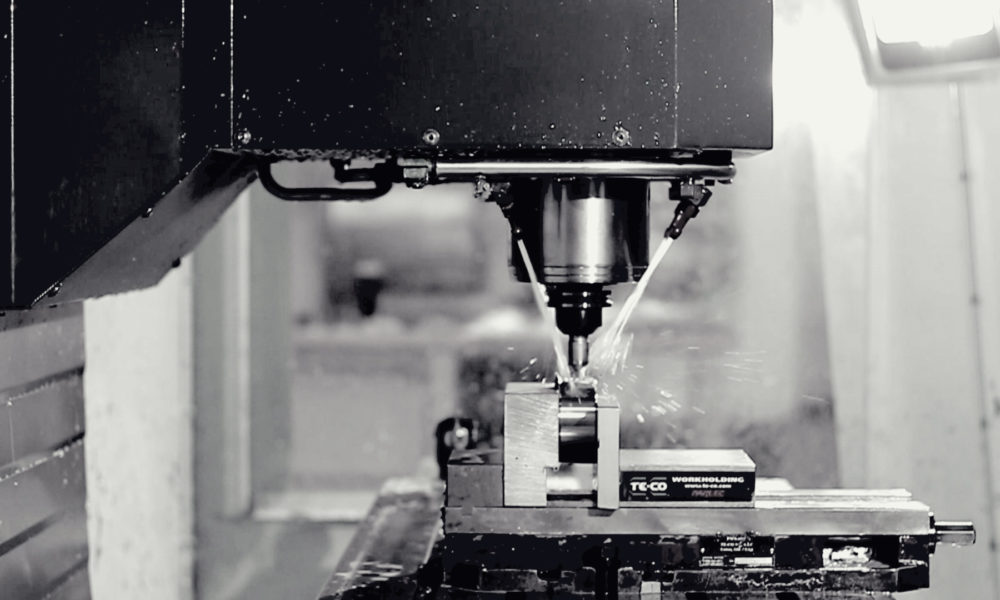
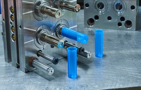
In addition to our sheet metal fabrication capabilities, we also specialize in CNC machining, injection molding, and 3D printing. Our manufacturing facilities are equipped with the latest equipment and technology. We can meet the needs of a variety of industries, including aerospace, automotive, medical, and consumer products.
When you partner with RapidDirect, you can trust that your products will be delivered on time, on budget, and with the highest quality standards. Contact us today to learn more about how we can help bring your design to life and accelerate your time to market.