Welding is one of the most efficient methods used in connecting different pieces of metal to make a single piece. It is a significant technique in sheet metal fabrication to complete a part’s manufacture. However, there is a possibility that welds can fail, causing welding defects.
Weld defects are common in sheet metal welding. These defects generally occur due to wrong welding methods or incorrect welding patterns. When they occur within a weld, they weaken the joint or cause complete product failure. Therefore, it is essential to understand the causes of these defects and proactively prevent them.
This article discusses the various types of welding defects, their causes, and how to prevent them. You will also learn the different methods of detecting invisible defects. The information here will help you distinguish between various defects and discontinuities. Let’s get into it!
What Are Welding Defects?
Defects in welding are flaws, irregularities, and imperfections formed in a given weldment, compromising its intended use or aesthetic appeal. Irregularities that compromise the weld are classified as weld defects according to ISO 6520. In contrast, flaws that do not compromise the weld are classified as weld discontinuities. Their acceptable limits are under ISO 5817 and 10042.
Defects often vary in size, shape, and extent based on the metal structure and the welding process. The major causes are the wrong choice of welding method or incorrect welding patterns. However, many other causes may lead to specific flaws in a weldment.
Weld defects may occur inside or outside the metal, weakening the joints or affecting their appearance. While some flaws can be within permissible limits, others may lead to product rejection. Thus, it is essential to avoid weld failure.
Types of Welding Defects
Welding faults and defects can be categorized according to their location in the metal. They may be external or internal.
External Welding Defects
These are superficial or visual defects. They manifest on the surface of the metal weldment. External weld defects are usually detectable via visual inspection or other methods like Magnetic Particle Inspection (MPI) or Dye Liquid Penetrants (DPI). Typical examples are cracks, undercuts, overlaps, porosity, spatter, etc.
Internal Welding Defects
Internal defects occur within the metal material and are usually not open to the weld’s surface. It is often difficult to detect these defects with visual inspection and some non-destructive tests. However, they are detectable using methods like Ultrasonic Testing and Radiographic Testing (RT). Common examples include slag inclusions, incomplete penetration, incomplete fusion, etc.
16 Common Types of Weld Defects
In sheet metal fabrication, improper welding can lead to several defects. This overview covers common issues, their causes, and remedies to ensure quality and durability.
#1 Weld Crack
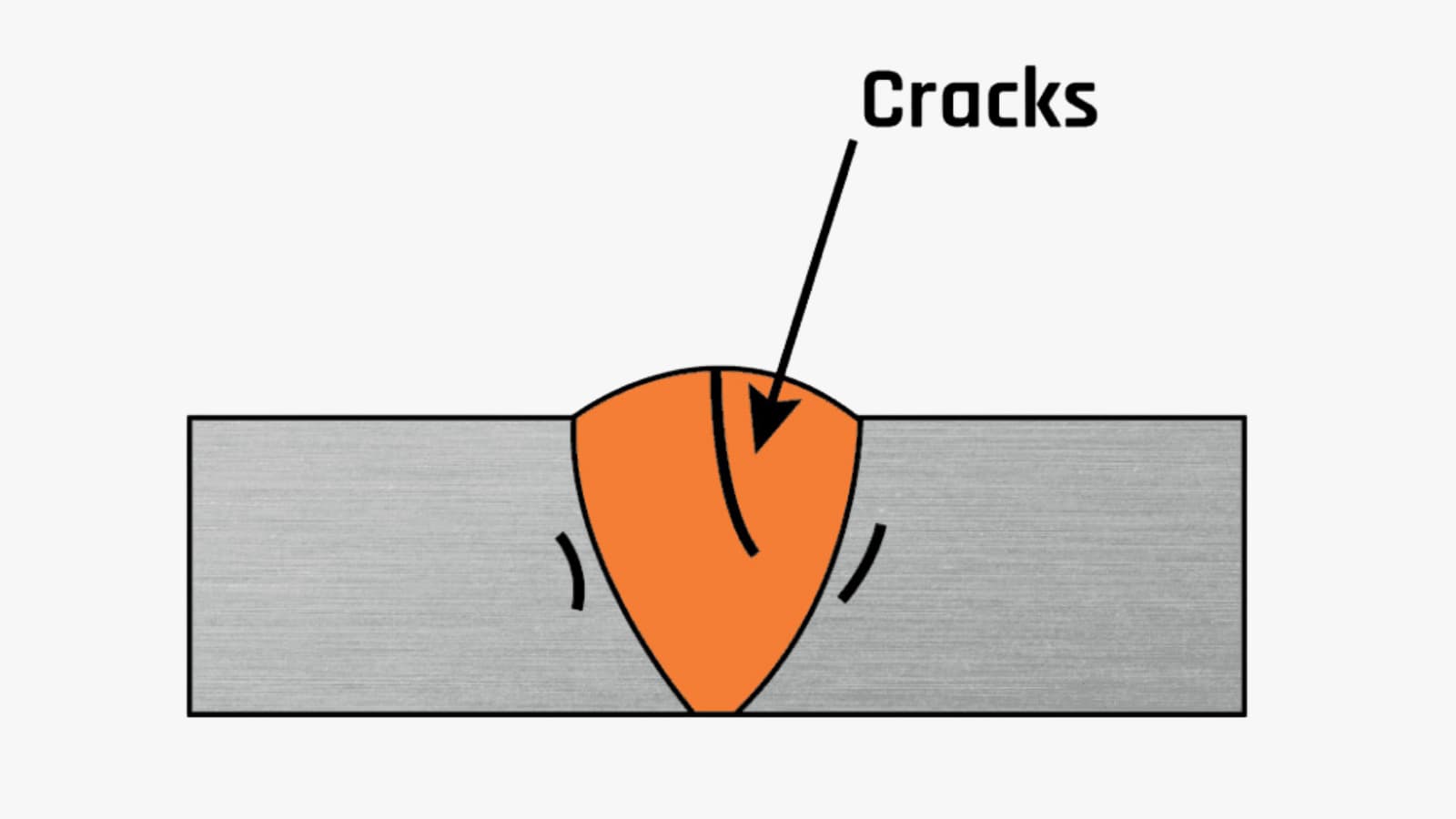
Cracks are perhaps the most unwanted welding defects. They are imperfections produced due to the local rupture from the effects of stresses and cooling. They are often significant because their geometry creates a large stress concentration at the tip of the crack. Therefore, the weldment is prone to fracture. Welding cracks can come in various sizes, shapes, and types, including:
- Longitudinal
- Transverse
- Crater
- Radiating
- Branching
Depending on the temperature they occur, cracks can be:
Hot Cracks
These occur during the solidification and crystallization of weld joints. At this stage, the temperature is often over 10,000 degrees Celsius. They can either be solidification cracks or liquation cracks. The former occurs when the metal contains high impurity or carbon content or when there is a disruption in heat flow. On the other hand, liquefication cracks occur due to increased heating temperature. This causes the liquefaction of constituents with low melting points.
Cold Cracks
These are “delayed” cracking defects that develop after the solidification of weld metal. They can occur many days after welding is completed. These types of cracks often lie parallel to the fusion boundary. Residual tensile stress may also cause the cracks to grow away from the fusion boundary. Cold cracks occur mainly due to a lack of preheating, high stresses, low temperature, high hydrogen content, susceptible material structure, etc.
Causes Of Weld Crack
- Poor ductility or contamination of given base metals.
- Combining high welding speed with low current.
- High residual stress solidification from shrinkage.
- Lack of preheating before starting welding.
- The high content of sulfur and carbon in base metals.
- Using hydrogen as shielding gas for welding ferrous metals.
Remedies for Weld Crack
- Use suitable metal materials and clean their surfaces before welding.
- Use the right welding speed and current.
- Preheat the base metal and reduce the cooling speed joint.
- Use the appropriate sulfur and carbon mixture.
- Reduce the gap between weld joints.
#2 Crater
Craters are special kinds of cracks that occur after the welding process before the completion of weld joints. It often occurs due to improper filling of the crater before breaking the arc. This leads to faster cooling of the outer edges than the crater. Insufficient volume of the weld may prevent it from overcoming metal shrinkage. As a result, a crater crack defect in the welding process is formed.
Causes of Crater
- Improper filling of the crater.
- Incorrect torch angle.
- Wrong choice of welding technique.
Remedies for Crater
- Ensure proper filling of the crater.
- Use a suitable torch angle for lowering stress on the metal. The torch angle for wire welding should be between 10 to 15 degrees in the direction of the weld. On the other hand, you should maintain an angle of 20 to 30 degrees (in the dragging direction) for stick welding. With a fillet weld, hold the wire or rod at 45 degrees between the metal pieces.
- Use a small electrode.
- Choose the correct welding technique.
#3 Undercut
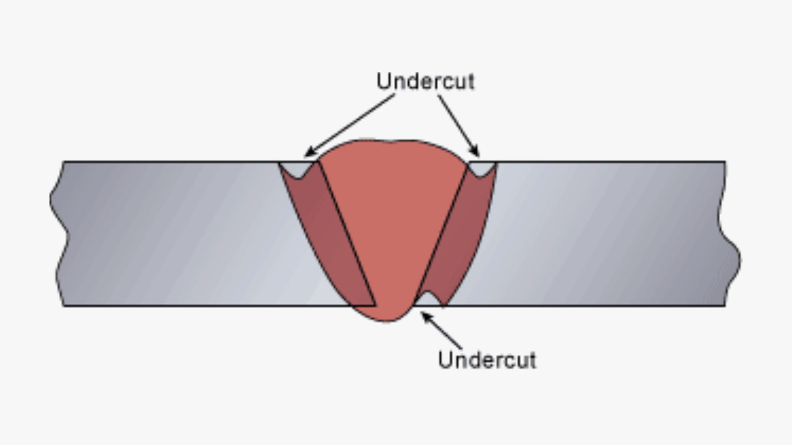
Undercut defects are irregular grooves formed in the shape of notches on the base metal. They occur due to the melting of the base of metal away from the weld zone and are characterized based on their length, depth, and sharpness. Undercut defects in welding run parallel to the weldment, causing a loss in thickness. As a result, the weld joint becomes more susceptible to fatigue. The types of undercuts are:
- Continuous undercut
- Inter-run undercut
- Intermediate undercut
Causes of Undercut
- Using too high voltage or too fast weld speed, causing melting at the top edge.
- High arc voltage.
- Wrong electrode angle or too large electrode.
- Using the wrong filler metal.
- Incorrect selection of shielding gas.
Remedies for Undercut
- Reduce travel speed and power input.
- Lower the arc voltage or reduce the arc length. The voltage should typically be between 15 to 30 volts. The welding arc length should not be more than the diameter of the electrode core.
- Keep the electrode angle between 30 to 45 degrees on the standing leg.
- Use the proper gas mixture based on metal type and thickness.
- Weld in flat positions.
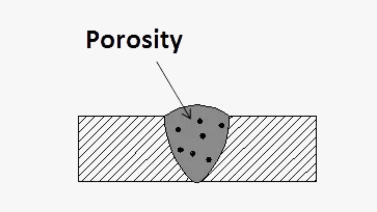
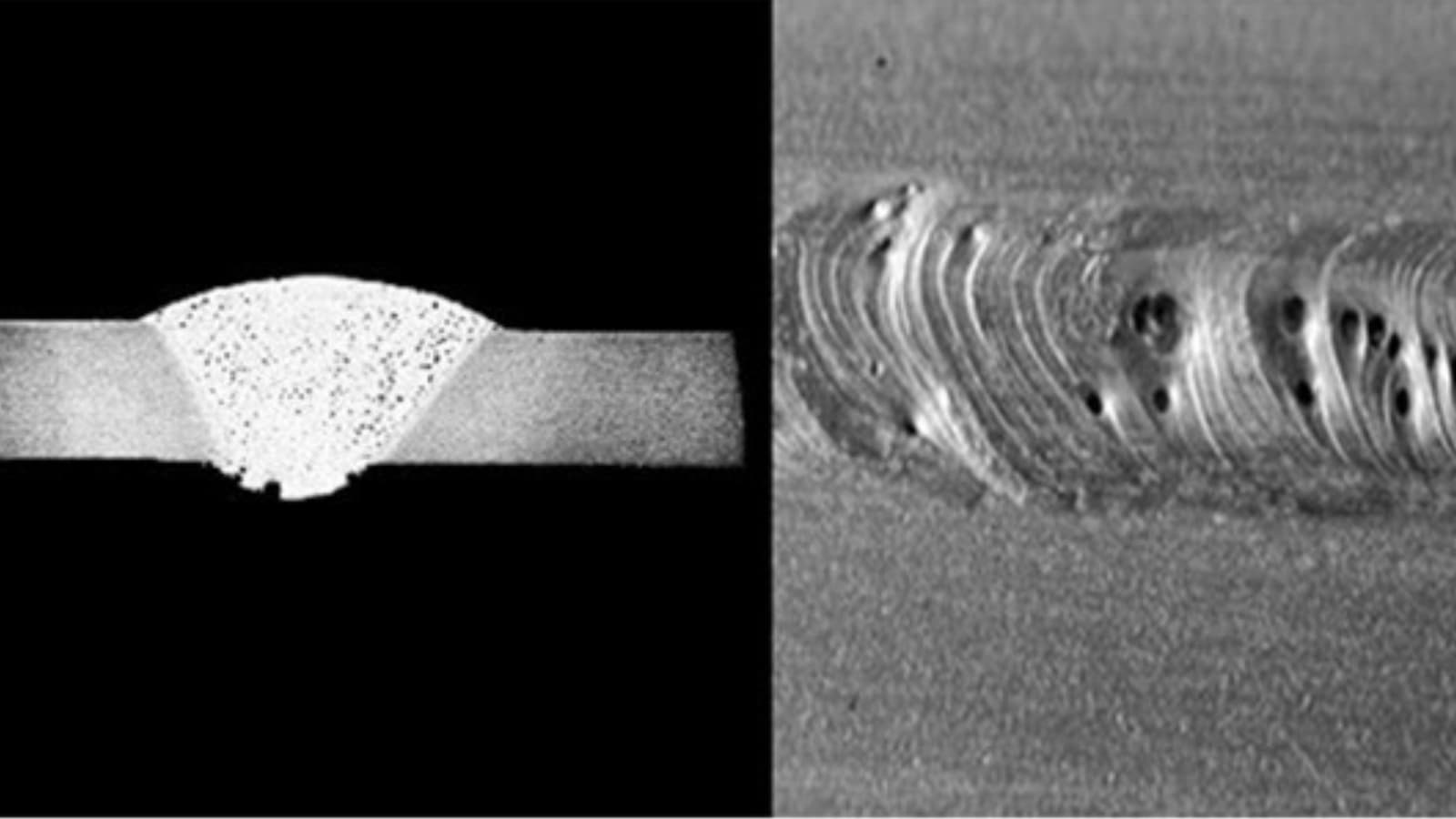
#4 Porosity
Also known as wormhole welds, porosity defects occur when there is an entrapment of air or gas bubbles in the weld. The welding process often generates gases like hydrogen, carbon dioxide, and steam. A cross-section of porous weld beads often resembles a sponge with an accumulation of trapped air bubbles.
The entrapped gases may be localized in a specific location or uniformly distributed in the weld. These gas bubbles can weaken the joint of the weld metal, predisposing them to fatigue and damage. Depending on their formation, these orbital welding errors can occur as:
- Gas Porosity. This is a small, spherical-shaped cavity generated from trapped gases. The various forms include surface pores, elongated cavities, linear porosity, etc.
- Worm Holes. These are elongated or tubular cavities formed during the solidification of trapped gases. You can see them as single holes or a group of holes throughout the weld surface.
- Surface Porosity. This is a kind of porosity that breaks the surface of the weld metal.
Causes of Porosity
- Inadequate coating of electrode or use of corroded electrode.
- Presence of grease, oil, water, rust, or hydrocarbon on the weld surface.
- Using incorrect shielding gas.
- Too high arc voltage or gas flow. The voltage should typically be between 15 to 30 volts.
- Poor surface treatment of base metal.
Remedies for Porosity
- Choose the suitable electrode and filler material.
- Ensure proper cleaning of the base metal and prevent pollutants from entering the welding area.
- To enhance the welding process and facilitate gas escape, adjusting the welding speed is crucial, as it varies across different welding techniques. For example, MIG welding is most effective at a travel speed of 14 to 19 inches per minute (IPM), while TIG welding achieves optimal results at a slower pace of 4 to 6 IPM.
- Configure the gas flow meter to the correct flow settings. Depending on the welding technique, the gas flow should be between 22 to 30 cubic feet per hour (CFH).
#5 Spatter
Spatters consist of metal particles expelled from the welding arc, commonly found in ARC, GAS, and tack welding processes. They can also appear, though less frequently, in MIG welding. These particles typically adhere along the weld bead or within joint designs, marking a distinct type of welding defect.
Spatters that accumulate in the nozzle may detach and damage the weld bead. They can also cause accidents for handlers if the spatter projections are sharp.
Causes of Spatter
- Too low voltage and too high amperage current settings.
- Wrong choice of shielding gas.
- Rigid electrode working angle.
- Using a wet electrode and a larger arc length.
- Contamination of metal surface.
Remedies for Spatter
- Use the right polarity and adjust the weld current.
- Use the proper shield gas.
- Increase electrode angle and decrease arc length.
- Clean the metal surface before welding.
#6 Overlap
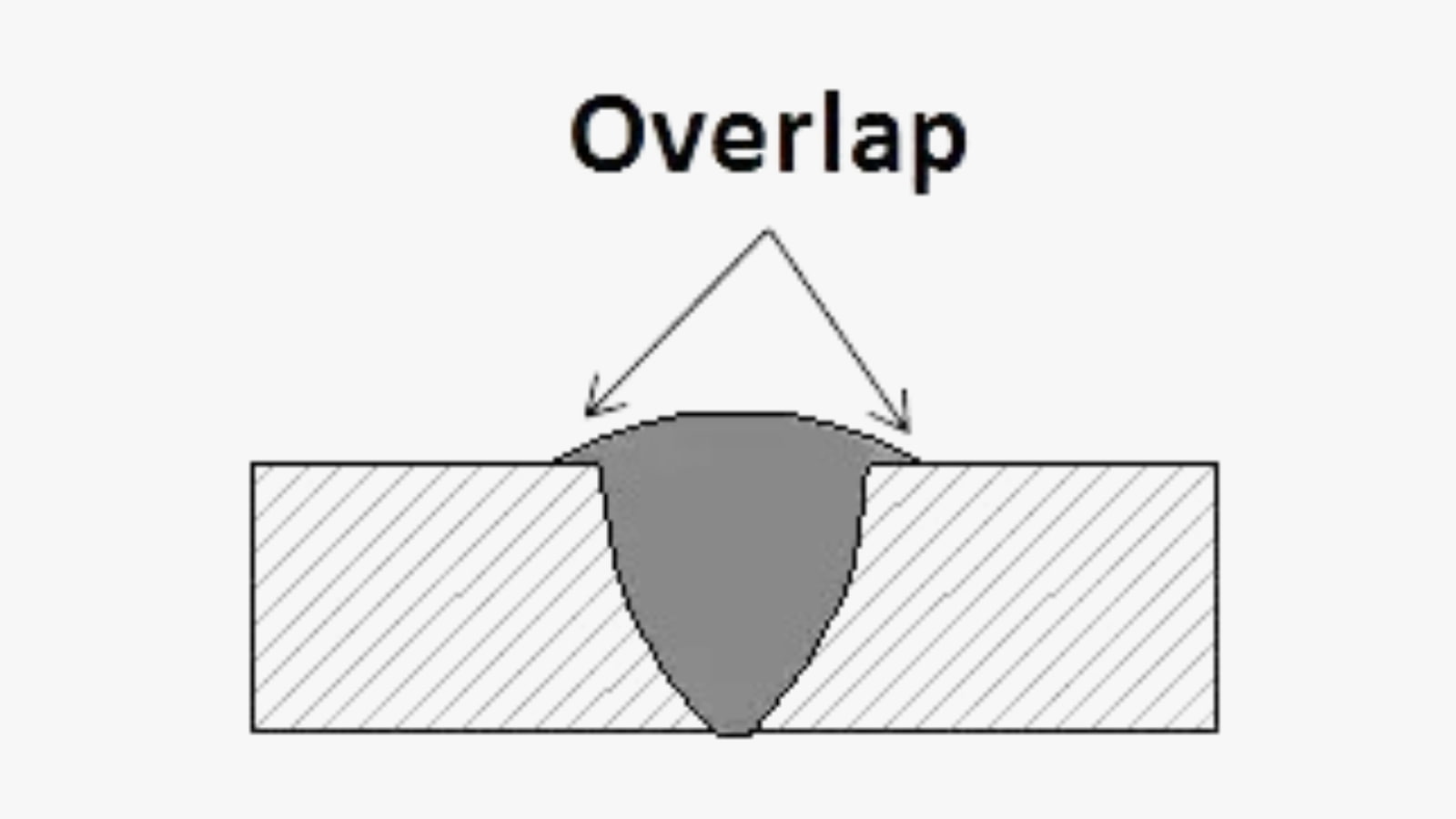
A weld overlap is a defect where the filler material at the weld’s toe covers the metal without bonding. In this case, the weld pool flows excessively and extends beyond the toe. The weld metal forms an angle below 90 degrees when this condition happens.
Causes of Overlap
- Using the wrong welding technique.
- Varying electrode angle.
- Employing large-sized electrodes.
- High welding current or heat input.
Remedies for Overlap
- Choose the proper welding technique for optimal arc length.
- Maintain the right electrode angle.
- Avoid using large-sized electrodes.
- Try to weld in flat positions.
- Use low heat input or welding current.
#7 Lamellar Tearing
Lamellar tearing welding fault usually occurs at the bottom of welded rolled steel plates. Their distinguishing feature is a crack with a terraced appearance. Lamellar tearing occurs when there is a thermal contraction within the steel plate. It can also be found outside heat-affected zones, often parallel to weld fusion boundaries.
Causes of Lamellar Tearing
- Weld metal deposits on surfaces with optimum cohesion.
- Improper material selection and welding orientation.
Remedies for Lamellar Tearing
- Ensure welding is done at the end of the fabrication.
- Select the best quality materials and use the right welding orientation.
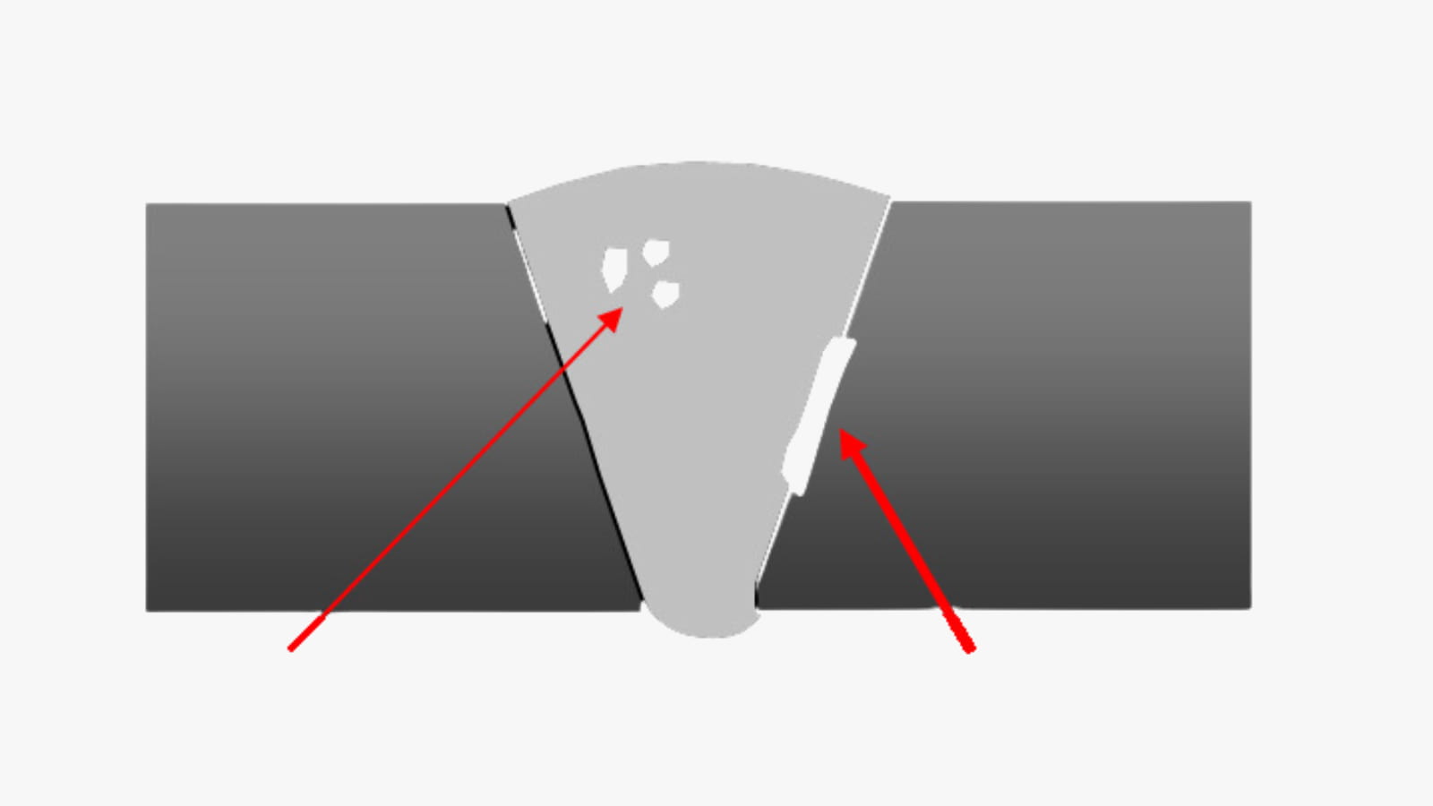
#8 Slag Inclusion
Slags, hazardous byproducts, emerge in various processes such as shielded metal arc, stick, flux-core arc, and submerged arc techniques. They often appear as trapped impurities within or on the surface of the welded areas.
Source from: leniran.blogspot.com
They occur when you use a flux (solid shielding material) during welding. When the flux melts on the surface of the weld or within the weld region, these weld defects can occur. The presence of slags affects the metal’s weldability and toughness. As a result, they decrease the structural performance of the weld.
Causes of Slag Inclusions
- Incorrect electrode angle.
- Using very small welding current density.
- Allowing the weld to cool too fast.
- Improper cleaning of previous weld layers.
- Insufficient space for puddles of molten welds.
- Too fast welding speed.
Remedies for Slag Inclusions
- Adjust the electrode angle and travel rate.
- Increase the current density to the appropriate value.
- Prevent rapid cooling.
- Clean weld bed surfaces before depositing the next layer.
- Redesign joints to ensure there is sufficient space for the proper use of a puddle of molten welds.
- Ensure optimal welding speed.
#9 Incomplete Fusion
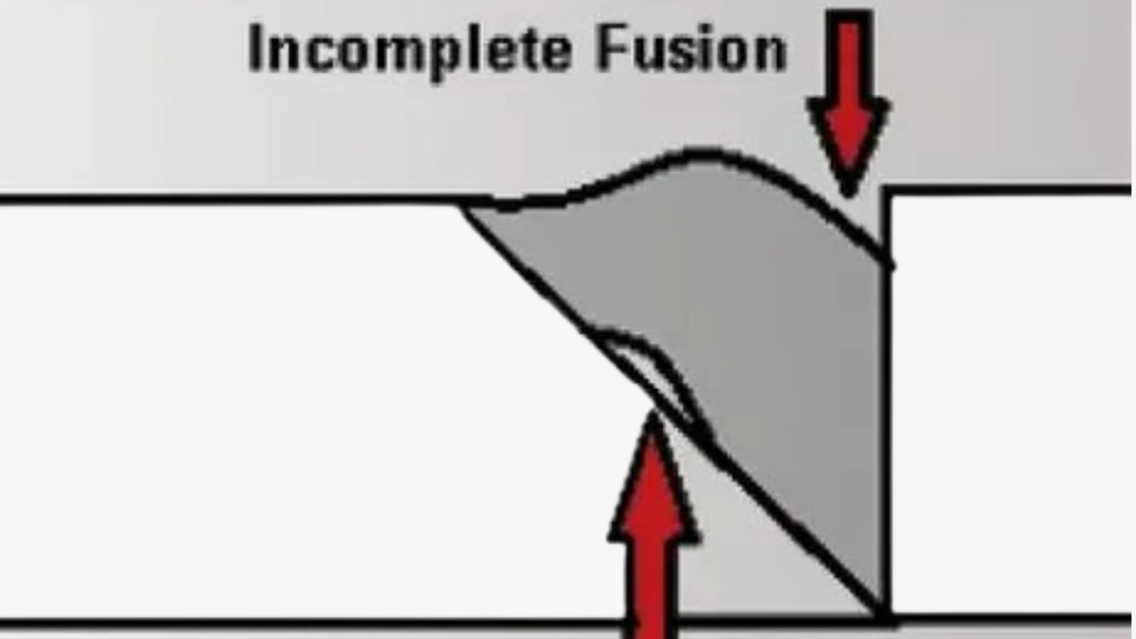
Also known as lack of fusion, this weld defect occurs due to inaccurate welding that results in unfilled gaps. It may be a result of the following:
- Lack of fusion between the parent metal and the weld metal at the weld’s root.
- Lack of sidewall fusion between parent metal and weld metal at the sidewall weld.
- Lack of inter-run fusion between adjacent layers of weld metals during multi-run welding.
Although this is an internal welding defect, you can also see incomplete fusion in welding on the outer surface. This happens when there is an improper fusion of the outer sidewall with the parent metal.
Causes of Incomplete Fusion
- Low heat input.
- Contamination of the metal surface.
- Using incorrect electrode diameters for the specific material thickness.
- Too fast travel speed.
- Large weld pools moving ahead of the arc.
Remedies for Incomplete Fusion
- Use proper heat input.
- Clean the welding area and metal surface before welding.
- Choose the right electrode diameter that fits the material thickness.
- Optimize the travel speed.
- Use an adequate weld pool that does not flood the arc.
#10 Incomplete Penetration
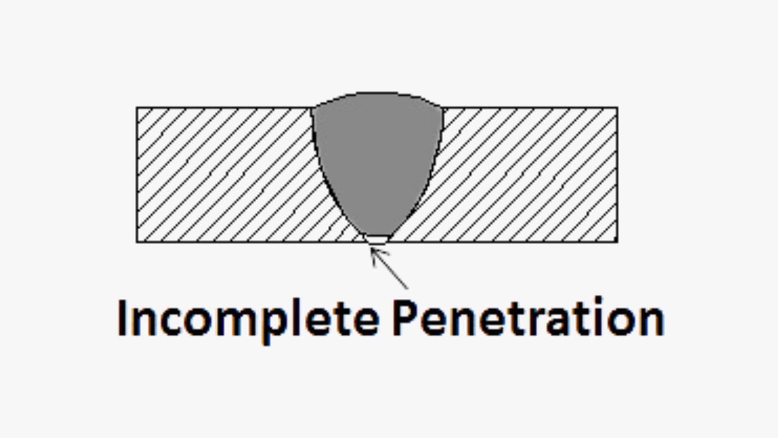
In welding, penetration is the distance from the upper surface of the base metal to the maximum weld extent. Incomplete penetration occurs when the metal groove is too narrow and is not filled. As a result, the weld metal does not entirely spread through or get to the bottom of the weld joint. This reduces the strength of the weld joint and causes weld failure.
Causes of Incomplete Penetration
- Improper joint alignment.
- Having too much space between the weld.
- Moving the welding bead too fast, results in little disposition of metal.
- Using too low amperage setting, preventing adequate melting of metal.
- Incorrect positioning of the electrode.
Remedies for Incomplete Penetration
- Use the correct joint geometry and proper alignment.
- Ensure enough weld metal deposition.
- Use proper amperage setting.
- Reduce the arc travel speed.
- Ensure accurate positioning of electrodes.
#11 Distortion
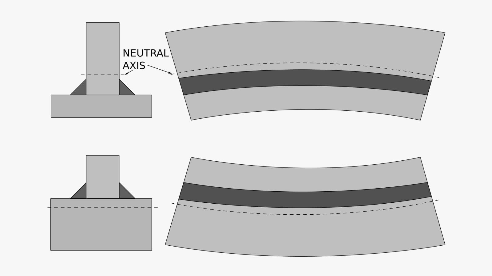
Distortion arises from the excessive heat applied during welding, leading to changes in the position and dimensions of metal plates. This defect is more pronounced in thinner plates, as their limited surface area hampers effective heat dissipation.
Causes of Distortion
- Varying temperature gradients during welding.
- Using an incorrect welding order.
- Slow arc travel speed.
- Too many welds pass with small diameter electrodes.
- High residual stress in the metal plate to be welded.
Remedies for Distortion
- Stick to an appropriate temperature gradient for welding.
- Use correct welding orders.
- Maintain an arc travel speed of 10 to 20 inches per minute for rotating workpieces, and 4 to 10 inches per minute for orbital welding equipment.
- Optimize the design for your sheet metal part for an adequate number of weld passes.
- Use the right amount of weld metal to decrease contraction forces.
#12 Burn Through
When there is an application of excessive heat during welding, the process may blow holes through the center of the metal. This type of weld defect is what we call a burn-through. It’s a common welding defect for thin metal sheets with less than 1/4-inch thickness. It may also occur with thicker metal stocks if the welding settings are too high or the torch movement is too slow.
Causes of Burn Through
- Too high welder settings for thick metal stocks.
- Significantly large gaps between metal pieces.
- The too-slow movement of the torch.
- Using incorrect wire sizes.
Remedies for Burn Through
- Avoid using too high a current or welder setting.
- Prevent having excessive gaps between metal plates.
- Optimal travel speed is key: for MIG welding, maintain 14 to 19 inches per minute, while orbital welding equipment should operate at 4 to 10 inches per minute.
- Avoid large bevel angles.
- Use tight wire sizes.
- Ensure adequate metal clamping and hold-down.
#13 Mechanical Damage
Mechanical damages, manifesting as indentations on parent metals or welds, often arise from mishaps in the welding process. These issues can stem from incorrect selection of welding techniques or improper use of welding tools.
Causes of Mechanical Damage
- Incorrect handling of electrode holders.
- Applying additional force during chipping.
- Inefficient grinder usage.
- Failure to engage the arc to the metal.
Remedies for Mechanical Damage
- Ensure proper handling of electrode holder after welding.
- Operate welding tools professionally.
- If required, hammering should be moderate.
- Engage the arc before welding.
#14 Excess Reinforcement
This weld defect occurs due to too much filler material in the weld joint. Excess reinforcement can occur as narrow, steep-side beads. It is usually a result of insufficient flux coating on the feed wire. Furthermore, the excess reinforcement can be ragged and uneven – mountain range reinforcement. In this case, the defect occurs due to excess flux or uneven travel speed.
Causes of Excess Reinforcement
- Insufficient or excess flux on the feed wire.
- Too fast or uneven feed wire travel speed.
- Varying voltage settings.
- Leaving large gaps between weld pieces.
Remedies for Excess Reinforcement
- Keep the torch moving at a proper speed.
- Set amperage correctly and prevent excess heat.
- Adjust voltage to ensure it is optimal.
- Align the weld pieces to prevent large gaps.
#15 Whiskers
Whisker defects are short-length electrode wires sticking out of the weld on the root side of the weld joint. They result from a protruding electrode wire from the weld pool’s leading edge.
These electrode wires compromise the aesthetic quality and mechanical properties of the weld. For example, whiskers are often seen as inclusions that weaken weld joints. They may inhibit the flow or cause equipment damage when used for piping applications.
Causes of Whiskers
- Using a high feed speed for electrode wire.
- Excessive travel speed.
Remedies for Whiskers
- Reduce the feed speed of the electrode wire.
- Ensure the travel speed remains optimal; avoid going too fast.
#16 Misalignment
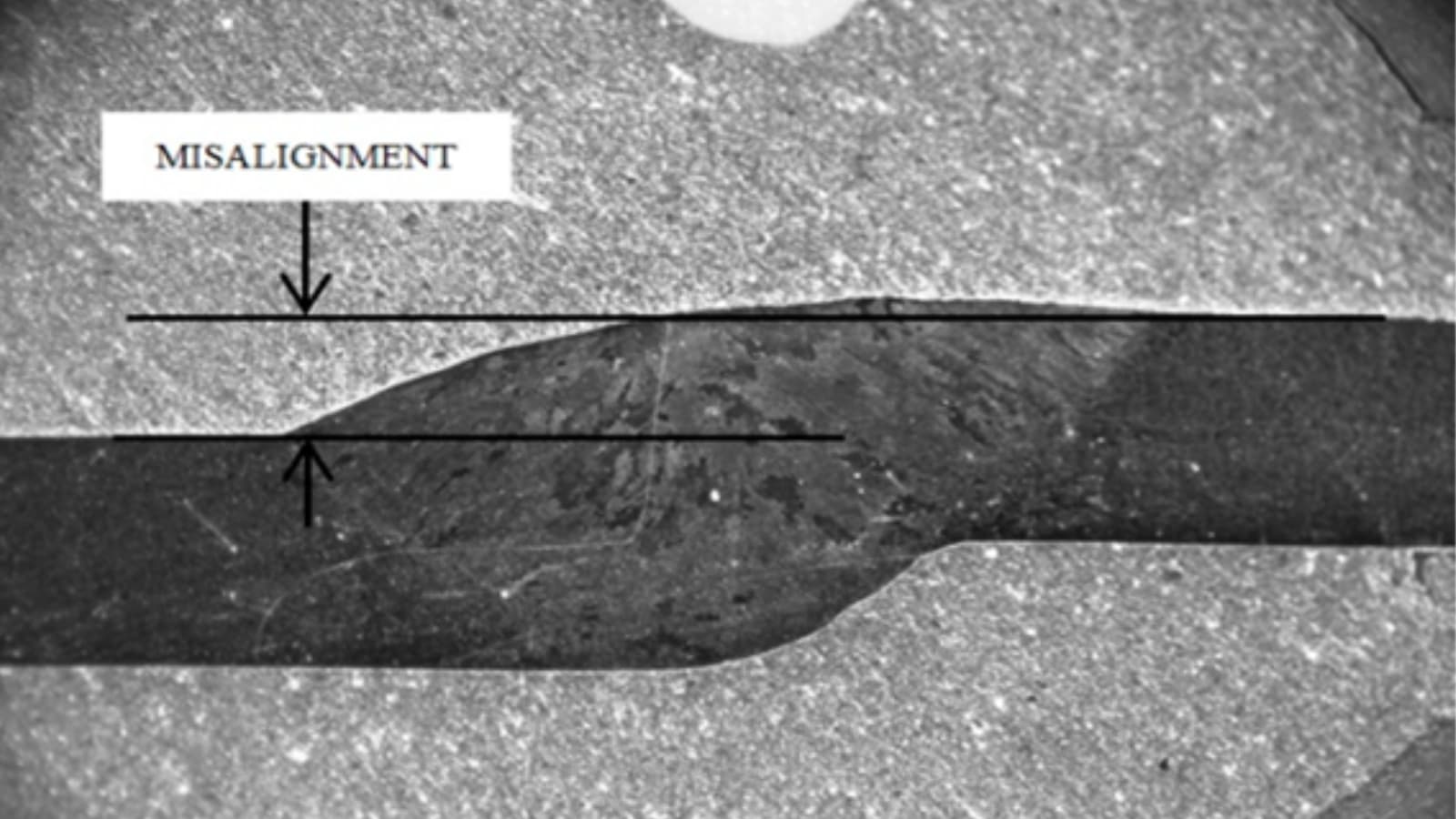
This welding defect occurs when the filler material decomposes in the welded joint. It is the difference between the external and/or internal heights of weld metal and base metal. You may see it as wavy or curvy spots on the weldment’s surface. A misalignment defect weakens the weld and reduces its ability to cope in high-fatigue environments.
Causes of Misalignment
- The too-rapid welding process.
- Improper choice of technique or handling.
- Inadequate placement of welding wire.
Remedies for Misalignment
- Apply a steady but efficient welding process.
- Use skilled experts and conduct adequate checks before welding.
- Keep the welding wire in the right position.
How to Detect Invisible Welding Defects – Non-Destructive Weld Testing and Inspections
Since welding involves the fusion of two or more metals, it may be difficult to detect internal welding defects using visual inspection. In this case, non-destructive testing (NDT) is a valuable option as it will show you the integrity of your weld. This process will keep the operations running smoothly without damaging any tools.
Magnetic Particle Inspection
This is one of the best methods of detecting surface cracks and weld defects that are too small to be detected by visual inspection. It is also an excellent choice for subsurface discontinuities in a weld. The process of electromagnetic particle inspection involves magnetizing the workpiece. It then uses a fluorescent solution to highlight the defects for proper documentation.
Ultrasonic Inspection
This inspection method uses high-frequency sound waves to check the interior and exterior of welded metals. It not only discovers defects and discontinuities in the weld but also measures the exact position of the defects. The instrument transmits high-frequency beams into the metal. Once it detects a weld defect, it bounces back to the ultrasonic welding machine to give a clear picture of a potential defect and its location. This allows for quick and easy fixing of the fault.
Radiographic Inspection
This technique is adaptable to various situations. It uses gamma rays or x-rays to inspect the interior of welds. The setup is simple and fast, presenting a vivid picture of defects on the screen of the X-ray machine.
How to Distinguish Between Weld Discontinuity and Weld Defects
Weld discontinuities are interruptions in the normal flow of a weldment’s structure. This may either be in the parent metal or the weld metal, and they occur due to wrong welding methods or patterns. These irregularities often differ from desired weld bead sizes, shapes, and intended quality. They can also be internal or external.
The following points distinguish welding defects from discontinuities:
- A weld would become a defect if the quality control department completely rejects the product.
- A discontinuity can survive field tests, but a defect cannot.
- Discontinuities often have a defined list of acceptable limits before rejection.
- Weld discontinuities are usually within acceptable manufacturing error margins, but defects must be repaired or rejected.
That said, if discontinuities exceed stated project limits, they may become a weld defect. Ultimately, it is vital to inspect welding processes using efficient methods.
Conclusion
Welding, a nuanced skill, requires a careful selection of techniques and precise execution. Defects in welding can compromise product quality and impact business performance. Understanding the different welding defects, their causes, and prevention methods is crucial for maintaining high standards.
Investing in the right tools and choosing the right metal welding partner is also crucial to meeting your manufacturing goals. RapidDirect offers reliable sheet metal welding services. Our robust facilities and strict quality inspection process ensure the production of high-quality welded parts. We also boast a highly skilled engineering team and professional technicians that ensure the right choice of materials and techniques to manufacture parts that meet your requirements. Contact us today, and let’s get your project started!